
"Wiring is like plumbing, but for electrons"
-me, 2017
One of the things I've come to dread in any project is wiring. This particular wiring job is by no means stellar, but works well enough to be worth writing about.
Starting at the front:

The steering wheel controls consist of an e-stop and a key switch. The e-stop is wired in series with the +12V line going to the logic and by extension, the 12V supply for the internal gate drives on the power module. Hitting the e-stop shuts down the microcontroller and gate drive, which safely floats the inverter phases.
The key is wired in series with the 12V going to the contactor control line - contactor power does not go through the e-stop. As interrupting high DC link currents damages the contactor, this switch is intended to act as a last line of defense in case the inverter has failed short or otherwise stopped responding to gate drive. In normal fault situations (throttle failure, firmware error) the e-stop suffices.
From the steering wheel, two runs of McMaster 8082K37 shielded cable connect the switches to a power distribution board...

...which I swear is the only reason the go-kart thinks about working at all. The sketchy CNC'ed board replaces what would be an even sketchier mass of wire junctions.
The HV contactor is a Kilovac Csonka EV200:

The datasheet claims it is rated for dozens of interruptions at 500+A but I don't believe it. The precharge resistor is bolted directly across the contactor, which has the benefit of precharging the DC link capacitor whenever the HV connector is plugged in, and the downside of slowly draining the traction pack should the HV connector be left unplugged.
The motors are wired to the inverter via 10AWG silicone wire stuffed inside a copper braid finger-trap shield:

I am not convinced the shield is doing much (it isn't terminated on either end, and terminating it didn't seem to affect noise), but keeping the phase leads in as small of a bundle as possible is important for reducing radiated noise.The shield is sealed to the wire bundle with 3M EPS-300 adhesive backed heatshrink, which upon heating forms a tough, watertight seal glued to the shield and wires.
Moving back to the inverter:

The phase lead bundles are attached to the bus capacitor tabs by zip-ties. As much of the exposed bus bar as possible is covered in liquid electrical tape to reduce the chance of inverter-induced incidents.
The capacitor itself is mounted via standoffs and slotted tabs to the inverter block:

The image above also shows the power module control cable, which is cut short and terminated in a DB-15 connector, then run through a 20" commercial shielded DB-15 cable to the logic board:
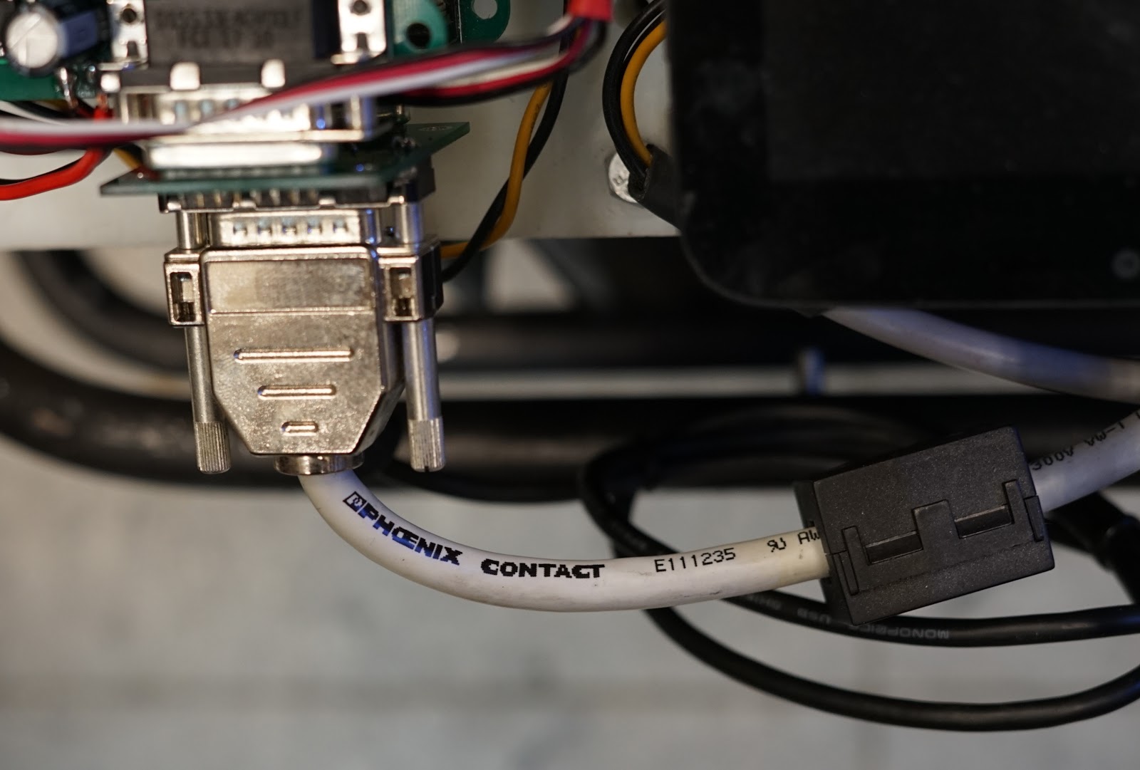
The Phoenix Contact cable was irritatingly expensive (~$50 on eBay), but it was rather difficult to find good shielded 15-wire cable.
Finally, the throttle is actuated through a bowden cable attached to the original go-kart throttle pedal (which operated a mechanical throttle on a carbureted engine). The throttle sensor is a GM brake position sensor:

The bowden cable is crimped to a standard copper ring terminal; please don't do this for an actual brake! It is only acceptable here because a cable failure causes the throttle to return to an off-position.
Excellent post thanks for sharing!
ReplyDeleteBlack Sink Perth
Fascinating read! It’s really interesting to think about the intersection of plumbing infrastructure and electrical safety — ensuring both systems are well installed and maintained makes a huge difference in long-term safety and performance.
ReplyDeleteIf you ever need help with gas appliance installation in Rockhampton, check out gas appliance installation Rockhampton for certified professionals who respect both safety and quality.