Sunday, October 1, 2017

2016 (Third Generation) Smart ForTwo Electric Drive Drive Unit Teardown

In addition to the Leaf drive unit, we recently acquired a Smart ForTwo drive unit. This one is somewhat of a unicorn - there are no images available, and little information other than it uses a Bosch SMG 180/120 motor and is 55KW. It is also of particular interest because the SMG 180/120 is an off-the-shelf motor and therefore should be easy to integrate into other vehicles; in addition, it has a distinguished heritage, being used in such applications as the Fiat 500e and the front axle of the Porsche 918.

Pre-shucking drive unit shot:


Integration is...poor. This makes sense since the Electric Drive was never a high volume vehicle - it was probably a compliance car designed to boost Mercedes' fleet mileage, and relied heavily on subsidies in EV-friendly states to break even.

Donor vehicle's tag, for future reference:


First, a diversion - the air conditioner compressor:


The compressor is fully integrated - DC and CAN in. Internally, it is a scroll compressor:


and an interior PM motor:


with a small inverter mounted to the back. Useful? Unlikely, unless you need an 370VDC air conditioner.

Time to move on to the meatier components. The integrated charger is a 6.6KW unit made by Lear:


Once again, severe coolant draining was required before we could proceed further:


Once the coolant was drained, the charger came off with a few bolts, revealing a nice self-contained unit:


We didn't look further into the charger, as we had minimal interest in turning it on, but it shouldn't be too hard to get running. Of note - the charger doesn't manage balancing, only AC-DC conversion.

Let's look at the inverter next. Aha! A part number! The inverter is an EFP 2-3, made by Continental and sold by Zytek.


A little bit of digging shows that it is a 235A continuous, 355A peak unit. A handful of bolts releases the inverter from the rest of the unit:


Very small and cute. The HV cables probably weigh more than the power electronics.

At this point we had released the motor-gearbox unit from the rest of the drive unit. Already looks promising - nice round motor, practically movable by a single person.

Hi Charles!
After splitting the gearbox from the motor...


...we are left with the most adorable little traction motor:


The mounting pattern is very convenient:


Though dangling the 32kg motor off of those tabs is probably less than wise.

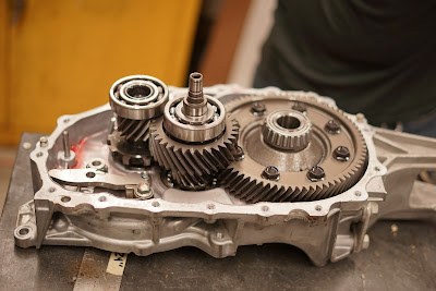
The gearbox is almost identical to the Leaf's, just smaller:


Internally, it is very similar:


We attempted to look inside the inverter next. It started out promising:


Oh hey, pin-style channels, presumably to reduce pressure drop.

The HV cable harness is...


...plugged in via giant blade terminals?!

Unfortunately, at this point we were defeated - the inverter housing had some concerning ribbon cables running to the internal boards, and it was very unclear how to split the housing without tearing up the cables.

Overall, this drive unit is very promising for small vehicle conversions. The poor integration is a blessing, as everything has sensible mounting holes, and there's a slim chance that it is possible to acquire the datasheet for the inverter and motor from their respective OEMs. Unfortunately 55/80KW (the latter is Bosch's peak rating for the motor) and 200Nm is not enough for a full car conversion - you would need a pair of them to get good power.

2013 (Second Generation) Nissan Leaf Drive Unit Teardown

We recently came across a Nissan Leaf drive unit:

Not shown: CHAdeMO charger blob
and of course had to look inside.

First, some outside dimensions for reference:


The drive unit is highly integrated; for example, the motor phase connections are short busbars:


Removing the dozen-odd screws and the three terminal screws allows us to separate the inverter from the motor...


...resulting in a very strange-looking U-shaped motor.

Pulling the next dozen bolts holding the differential and gearbox to the motor separates the gearbox from the motor:


A few more shots of the motor:


The natural next step was to look inside the gearbox...


...which unfortunately meant draining a liter of suspicious red Nissan Leaf fluid out first.

After that, it was simple enough to remove yet another dozen screws and split the gearbox housing:


Nothing much to see here, standard single stage helical gear going into an open differential. More pictures:


Overall reduction is a little over 8:1.

Next we look inside the inverter. First, a quick look at the waterblock channels:

Nothing to see here, standard cast channels.

Cracking the power electronics enclosure open required breaking through a lot of RTV sealant...


...revealing the gorgeous (and never-before-seen!) innards:


The inverter is much less dense than we had anticipated; the IGBT's have their own module (rather than being brazed straight to the waterblock), and there is a lot of empty space over the PM.


Controller is unfortunately based around a datasheet-less Renesas microcontroller, as are all Japanese automotive electronics.

Capacitor is 1088uF, 600V, SH film:


And a lot smaller than the one inside the 2nd-gen Prius.

Few more shots, including gate drive power supplies:


Overall, very well integrated with few surprises. I would not even dream of reprogramming this inverter, as dialing in the motor tuning for something this large would be very involved. My one comment is that this motor is probably good for much more than 80KW peak - judging by its size I would venture to say it is a 200KW-class motor.

Friday, September 8, 2017

Field Weakening, Part 1

Previously on Motor Diddlers, we learned how to optimize the torque produced by an IPM operating in the current-limited regime. We can't stay in this regime forever; at higher RPM's, all motors enter a voltage-limited operating regime.

What's surprising is how quickly IPM's become voltage-limited. Using the data from the last post, we can plot the maximum achievable current versus speed:


The "base speed" of the motor is very low, about 800 rad/s (2500 RPM). Furthermore, we quickly run out of volts past base speed; the motor cannot turn much faster than 1500 rad/s (5000 RPM) if we constrain ourselves to the MTPA trajectory. This is a result of the much higher inductance of an IPM; at high electrical frequencies this inductive impedance limits how much current we can put into the stator.

Fortunately, we can use this higher inductance to our advantage. Recall that \(V_q=R_s I_q+\omega L_d I_d+\omega\lambda\); this means that if \(I_d\) is negative, we can cancel out the \(\omega\lambda\) term (what would conventionally be called "back EMF" in a surface PM machine) in the expression for \(V_q\). On a surface PM machine, this current would be wasted; however, if \(L_d < L_q\), the \((L_d-L_q)I_d I_q\) term in the torque equation will generated positive torque! Furthermore, the \(L_d/\lambda\) ratio is often an order of magnitude higher for IPM's, which greatly reduces the amount of d-axis current required to cancel out the flux linkage. This is, in a nutshell, why IPM's field weaken much better than their surface PM counterparts.

It is fairly straightforward to compute the optimal field-weakening trajectory:

Starting from the motor equations $$
\begin{array}{lcl}
\tau=\frac{3}{2}n_p(\lambda I_q+(L_d-L_q)I_d I_q)\\
V_d=R_s I_d-\omega L_q I_q\\
V_q=R_s I_q+\omega L_d I_d+\omega\lambda\\
V_s=\sqrt{V_d^2+V_q^2}\\
I_s=\sqrt{I_d^2+I_q^2}
\end{array}
$$ we note that in the voltage limited operating regime, maximum torque must be achieved when the voltage vector is on the boundary of the allowable area, in which case the optimization problem becomes an equality: $$
\begin{cases}
\frac{3}{2}n_p(\lambda I_q+(L_d-L_q)I_d I_q) = \tau_0\\
(R_s I_d-\omega L_q I_q)^2 + (R_s I_q+\omega L_d I_d+\omega\lambda)^2 = V_0^2
\end{cases}
$$ If we ignore saturation, this system is the intersection of a constant-torque hyperbola (which is independent of speed) and a series of shrinking ellipses.


This system is polynomial (and in fact only a quartic) and can be solved in many ways. For example, one element of the reduced Groebner basis of the ideal generated by the two equations is the very long $$
(L_d-L_q)^2(R_s^2+L_q^2w^2)I_q^4 +
(L_q^2\lambda^2\omega^2+R_s^2\lambda^2+(L_d-L_q)^2(2R_s\tau_0\omega-V_0^2))I_q^2-
2\lambda\tau_0(R_s^2+L_d L_q\omega^2)+
R_s^2\tau_0^2+L_d^2\tau_0^2\omega^2
$$ where we have included the factor of \(3/2n_p\) in \(\tau_0\) for brevity's sake. The roots of this polynomial are easily found with a variety of numeric or analytic methods; in the case of multiple real solutions the correct one is the \((I_d,I_q)\) vector with the shortest length.
Unfortunately, the system is no longer polynomial if the motor saturates (that is, \(L_d\) and \(L_q\) are functions \(l_d(I_d,I_q)\), \(l_q(I_d,I_q)\) of the axis currents). In order to solve the system in this case, we will have to turn to more complicated (and less reliable) numeric methods, the nature of which will be the subject of the next post in this series.