Tuesday, September 21, 2021

A Small Astrograph with a Large Payload


Building a large telescope is hard; designing a small telescope is hard. What exactly do I mean by that? Well, there are parts of the telescope that don't scale well with size, for example, the instrument payload, the filters, or the focusing actuators. More often than not, a design which works well on a 1m-class instrument fails to scale down to a 300mm-class instrument because the payload is incompatible with the mechanics, or is so large that it fills the clear aperture of the instrument.

A small telescope should also be...small. A good example of this is the remarkable unpopularity of equatorially-mounted Newtonians; a parabolic mirror with a 3-element corrector offers fast focal ratios and good performance, but an f/4 Newtonian is four times longer than it is wide, which gets unwieldy even for a 300mm diameter instrument.

The Argument for Cassegrain Focus

Prime focus instruments are popular as survey instruments in professional observatories. However, they fail to meet the needs of small instruments because of:

  • Excessive central obscuration. A 5-position, 2" filter wheel is about 200mm in diameter. In order to maintain a reasonable central obstruction, a 400mm clear aperture instrument is required which is marginally "small". Any larger-diameter instrumentation requires a 0.6m+ class instrument which is outside of the scope of many installations.
  • Unreasonable length. The fastest commercially available paraboloids are about f/3. Anything faster is special-order and very expensive. An f/3 prime focus system is actually longer than 3 times its diameter because of the equipment required to support the instrument payload.
  • Challenging focusing. For a very large system, actuating the instrument is the correct method for focusing because even the secondary mirror will be several tons. For a small system, reliably actuating 10+ kg of payload with no tilt or slip in a cost-effective fashion is rather unpleasant.
  • Too fast. A short prime focus system is necessarily very fast, complicating filter selection. A very fast system also performs poorly combined with scientific sensors with large pixels.
The commercially available prime focus instruments (Celestron RASA/Starizona Hyperstar, Hubble HNA, Sharpstar HNT) are designed for use with small, moderately-cooled CMOS cameras, possibly with a filter wheel in case of the Newtonian configurations. The RASA is wholly unsuited for narrowband imaging because a filter wheel would almost cover the entire aperture.

A Cassegrain system solves these issues by (1) allowing for moving-secondary focusing (2) roughly decoupling focal ratio from tube length and (3) moving the focal plane to be outside of the light path.

The 50% Central Obstruction

A 50% CO sounds bad, but by area the light loss is 25%, or less than half a stop. A 300mm nominal instrument with a 50% CO has the light gathering capacity of a 260mm system, which is pretty reasonable. The 50% CO also makes sizing the system an interesting exercise, because at some point the payload will be smaller than the secondary and prime focus makes sense again.

The Design

The Busack Medial Cassegrain is a really nice telescope that this design draws inspiration from, but it requires two full-aperture elements each with two polished sides that makes it ill-suited to mass production. Instead, we build the system as a Schmidt Corrector, an f/2 spherical mirror, and a 4E/3G integrated corrector. There's really nothing to it - by allowing the CO to grow and using the corrector to deal with the increasing aberrations, an f/4 SCT is entirely within the realm of possibility. There's a ton of freedom in the basic design, the present example makes the following tradeoffs:
  • f/4 overall system allowing for the use of an f/2 primary (which we know is cheaply manufacturable based on existing SCT's). f/4 also allows for the use of commodity narrowband filters.
  • 400mm overall tube length (not counting back focus) is a good balance between mechanical length and aberrations. 50mm between the corrector and secondary allows ample space for an internally-mounted focus actuator.
  • 160mm back focus allows for generous amounts of instrumentation including filters, tip-tilt correction, and even deformable mirrors.
  • Integrated Schmidt corrector allows for good performance with no optical compromises.
  • Corrector lenses are under 90mm in diameter and made from BK7 and SF11 glass, all easily fabricated using modern computer-controlled polishing.
The total length of the system could also be shortened, and the corrector diameters reduced, by increasing the primary-secondary separation and reducing the back focus, depending on instrument needs. Overall performance is quite good, achieving 4um spots sizes in the center and a high MTF across the field.


Actually Building It?!

Obviously, you are not going to make a 300mm Schmidt corrector and a four-element, 90mm correction assembly at home. This design is probably buildable via standard optical supply chains (the hardest part would be getting someone who is neither Celestron nor Meade to build Schmidt correctors). The correction assembly should also be further improved - there are a huge number of choices for its configuration and the 'correct' one is probably the one that is most manufacturing-friendly.

Shoot me an e-mail in case you are crazy and want to do something with the prescription for this design!

Friday, July 9, 2021

GCA 6100C Wafer Stepper Part 2: the stages

The modern wafer scanner is a truck-sized contraption full of magnets, springs, and slabs of granite capable of accelerating at several g's while maintaining single-digit nanometer positioning accuracy. The motion systems contained within painstakingly try to optimize for dynamic performance by using active vibration dampening, voice coils, linear motors, and air bearings, all to increase the value of the machine for its owner (who spent a good fraction of a billion dollars on it).

As it turns out, a 80's stepper is none of these things. Scanners are immensely complex because they are dynamic systems - as the wafer moves in one direction, the reticle moves in the other direction, perfectly synchronized but four times faster. In contrast, steppers are allowed time to settle between steps, which allows for much more leeway in the motion system design. Throughput requirements were also lower; compare the 35 6" wph of an old stepper to the 230 12" wph of a modern scanner.

Old stepper stages are an instructive exercise in the design of a basic precision motion system; in fact, Dr. Trumper used to give this exact stage out as a controls exercise in 2.171. The GCA stages are also particularly interesting from a hardware perspective - they are carefully designed to achieve 40nm positioning accuracy using fairly commodity parts. The only precision parts seem to be the slides for the coarse stage, and even those are ground, not scraped.

The stage architecture

System overview

GCA steppers use a stacked stage architecture. Coarse positioning is done by two conventional mechanical bearing stages stacked on top of each other. Fine positioning is done by a single two-axis flexure stage. Rotational positioning, which only happens for alignment, is done using a simple open-loop, limited travel stage mounted on the fine stage. Focusing, which is done by changing the Z spacing between the lens and the wafer, is done by moving the optical column up and down with a linkage mechanism.

The position feedback system


The fine position feedback on GCA steppers is implemented through a two-axis HP 5501A heterodyne interferometer. Briefly, a stabilized HeNe laser is Zeeman split through a powerful magnet to create two adjacent lines separated by a few MHz with different polarizations. One of these lines is separated with a polarizing beam splitter and reflected off a moving mirror; this line is Doppler shifted due to the velocity of the moving mirror and beat against the stationary component to generate a signal. This signal is compared against a stationary REF signal to derive velocity and position measurements. Heterodyne interferometers are the preferred choice for metrology due to their insensitivity to ambient effects and power fluctuations.

The 5501A is the de facto choice for interferometric metrology; its successor the 5517 is still available from Keysight. A description of the system as found in the GCA steppers is as follows:

The laser points towards the rear of the stepper; a 10707A beam bender and a 10701A 50% beam splitter generate the two axes of excitation. The X and Y stages have identical measurement assemblies; the Y assembly is located to the rear of the stepper (behind the column) and the X assembly is located inside the laser housing. Both assemblies use a plane-mirror interferometer which differentially measures the wafer position against the optical column; the stationary mirror is a corner cube mounted to the column and the moving mirror is a 6" long dielectric quartz block mirror mounted to the wafer stage. The flats are precision shimmed to ensure orthogonality (since it is the orthogonality of the flats which determines the closed-loop orthogonality of the motion).

There are two additional position sensors in the system. The first is a sensor to measure the position of the fine stage relative to the coarse stage. Literature indicates that this is an LVDT, but on the 6100C it appears to be implemented as two photodiodes outputting a sin/cos type signal. The second is a brushed tachometer on each of the coarse stage drive motors, which is used for loop closure by the stock controller.

The coarse stage

The purpose of the coarse stage is to position the fine stage to within 0.001" of its final position. The stage is built as a pair of stacked plain-bearing stages; these stages are driven by brushed DC motors with brushed tachometers for velocity feedback. The motors go through a right-angle gearbox comprising of a bevel gear and several spur gear stages before being coupled by a flexible coupling to a long drive shaft which turns a pinion positioned near the center of each stage. This pinion drives a brass rack mounted to the stage which generates the final motions.

The fine stage


The fine stage is constructed as a parallel two-axis flexure stage with a few hundred microns of travel on each axis. The flexures are constructed from discrete parts; the stage is made from cast iron and the flexures themselves are constructed from blue spring steel. Actuation is by moving-coil voice coil motors with samarium-cobalt magnets, and position is read directly from the interferometer system.

The theta stage


The theta stage is a limited travel stage based on a tangent arm design. A (very small) Faulhaber Minimotor is coupled into a high reduction gearbox, which drives a worm gear that turns a segment of a worm wheel. The worm wheel pushes on a linkage which rotates the wafer stage about a pivot point.

Rotation control is entirely open-loop - the wafer is rotated once during the alignment process based on the fiducials observed through the alignment microscopes. A slow open-loop system is acceptable given that the speed of rotational alignment does not significantly affect wafer throughput.

The Z mechanism

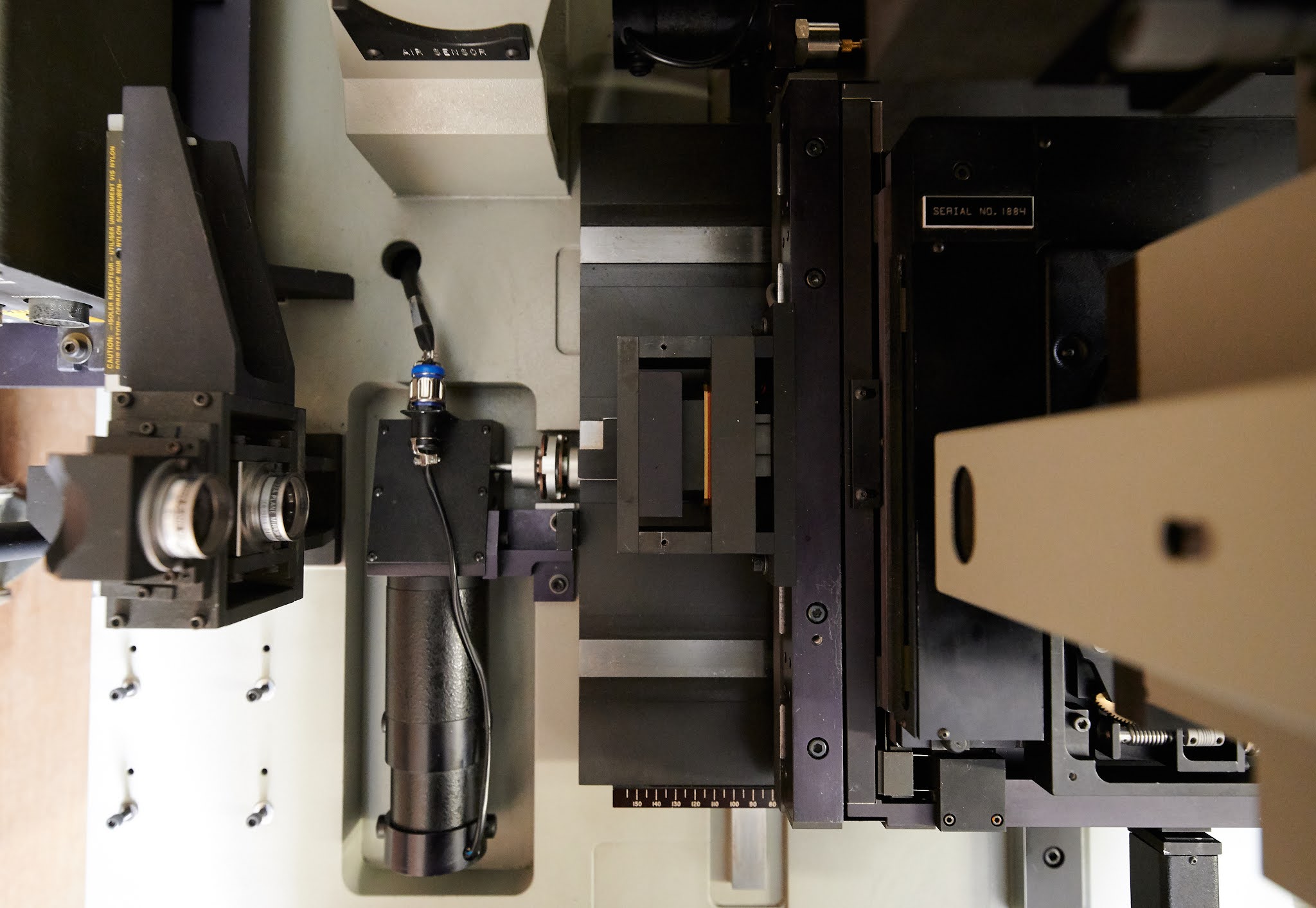
The focusing mechanism is a limited-travel (according to literature, about 600um) flexure mechanism. The entire optical column is suspended on two large spring steel plates; a stiff spring counterbalances the weight of the column. A voice coil motor (identical to the fine stage VCMs) actuates a linkage mechanism which moves the column up and down.

Adjusting the mechanism is a bit subtle. The white rod sticking out is actually a tensioning mechanism for the counterbalance; it is possible to aggressively tension the spring to stiffen the assembly for transport. The cap at the end of the rod can be removed to reveal a nut and a piece of threaded rod with a flathead in it. You want to hold the rod in place with a screwdriver and crank on the nut with a wrench until the column just barely 'floats' in place.

Incidentally, this mechanism also reveals a fairly severe weakness of the focusing system - it is extremely undamped. Any disturbances on the column cause the whole assembly to ring like a bell, with the only source of damping being the resistance of the VCM. I think (though there is some information to the contrary) that 6000-series GCA steppers focused once per wafer, relying on wafer leveling to keep the image in resist in focus between fields. Otherwise if the focusing had to be highly dynamic there could be problems.

Sunday, May 23, 2021

GCA 6100C Wafer Stepper Part 1: Intro and Maximus 1000 Light Source

The yellow lights make it look more legitimate

I have always wanted to expose a wafer. I'd written off making my own transistors long ago (nothing that fits in a house is good for feature sizes small enough for interesting logic, and I'm not a good enough analog engineer to design interesting analog), but there are many useful optical and mechanical parts that can be made lithographically.

The usual route to home lithography is a microscope and a DLP, but the resultant ~2mm field sizes are not sufficient for mechanical parts and stitching a 20mm field out of 2mm subfields is very taxing on your motion system. Contact aligners are simple and perform well, but getting submicron resolution for interesting optical parts out of a contact aligner is challenging (the masks also get quite expensive).

The natural solution is to start with a stepper lens (which is basically a giant microscope objective with very bad color correction). There are a few variants - 1:10 lenses with a 10x10mm field, 1:5 lenses with a 14x14mm field, and 1:4 lenses, which weigh several hundred kg and have a 20x20mm field. Stepper lenses also come in several colors: g-line (436nm), i-line (365nm), and DUV (~250nm).

I wound up with a 1:5 g-line lens; the 1:5 lenses strike a good balance between performance and unwieldiness. I also had a set of stages pulled from a DNA sequencer good for a couple microns of resolution. The rough plan was to stack a fine stage on top of these and use a direct-viewing technique to perform alignment. However, the project quickly went south when I realized building an exposure tool entailed buying the parts out of an...exposure tool. Conveniently, a circa 1985 GCA DSW 6100C showed up for more or less scrap value near me, so one rigging operation later I was the proud owner of a genuine submicron stepper.

The DSW family of steppers are true classics; GCA Mann practically invented the commercial stepper in the late 70's. The GCA steppers remained more or less unchanged until the company's demise; everything from the g-line DSW 4800 to the AutoStep 200 shared a stage design, alignment system, and mechanical construction (unfortunately, they also all shared a terrible 70's-grade electronics package!). A number of GCA tools still survive in university fabs, mostly converted to manual operation. Briefly, the design consists of:

  • A cast-iron base with a cast-iron 'bridge' holding the optical column.
  • A stacked stage consisting of two coarse mechanical bearing stages driven by servomotors, two fine flexure stages constructed as a single unit driven by voice coil actuators, and a open-loop, limited-travel rotation stage driven by DC motors.
  • Feedback provided by an HP 5500-series interferometer that meters the displacement between two mirrors mounted to the optical column and two flats mounted to the fine stage.
  • A reticle alignment stage consisting of a small flexure actuator and fine-pitch screws for adjustment.
  • A focusing system using a photoelectric height sensor and a linkage mechanism that adjusts the entire optical column height (!) with a travel range of around 1mm.
  • An alignment system using two fixed microscopes to align the origin and rotation of the wafer.
  • A high-pressure mercury arc lamp with a homogenizer and filter (MAXIMUS) to illuminate the reticle with Kohler illumination of the appropriate wavelength.
My copy showed up in an interesting state of disrepair - the laser and alignment microscopes were missing (why anyone would want the alignment microscopes is beyond me), and the Maximus made rattling noises. The first step was to repair the light source.

Inside the Maximus 1000

Life before LEDs was bad. Arc lamps produce a concentrated point of light a few mm across, and turning that into uniform illumination across a 4" reticle is challenging. Now, normal people use a elliptical collector, a condenser lens, and a fly's-eye homogenizer to produce uniform illumination, but not GCA.

Instead, the inside of the Maximus looks like this:


The arc lamp goes in the center; the four identical assemblies each collect 1/4 of the arc lamp output.


The top left is a condenser lens assembly. The diagonal mirror is a cold mirror (it dumps IR into a heatsink not shown); the round filter below it is a narrowband filter for the design wavelength (in this case, 365nm). So far, reasonable. But, where you would usually see a homogenizer after the filter, there is instead a focusing lens. This lens focuses the lamp output into four fiber lightguides, which bundle into a single lightguide on the other end. The output of this lightguide is then imaged onto the reticle in the usual fashion by a illumination lens. This arrangement, while very complex, has a neat benefit: the characteristics of the illumination are solely determined by the light guide. The NA of the fibers sets the illumination field size, and the diameter of the output bundle determines the NA of the illumination. The illumination is perfectly uniform, since every fiber perfectly illuminates the whole field; missing fibers will only result in a slight overall loss of intensity.


As luck would have it, practically every screw in the Maximus was loose, and the bulb was snapped in half. The rebuild took a couple hours, and was greatly improved by removing the head from the stepper - dealing with loose lenses is much easier when you are not six feet off the ground (if by some chance you are reading this and also servicing a GCA stepper, removing the Maximus is easy - just pull the four socket head screws at the base of the condenser, un-route the shutter cables and lamp cables, and the unit lifts right off).

I haven't had a chance to check performance yet, as the bulb needs replacement. The Maximus uses Ushio USH-350DP bulbs. Of critical note: the USH-350DP is a two-screw-terminal designed for aligners. The Maximus uses a screw-on "bullet" on one end to convert it to a plug-in type; if you are changing bulbs, don't throw out the plug! 

Additional GCA resources

  • Here is a collection of various official GCA manuals scraped off the internet, mostly from university sites. The information in the manuals is helpful for understanding how the system works. If you are intent on actually using the stock GCA controller, the manuals are pretty much mandatory, since the PDP-based software is not very user friendly.
  • Here are various pieces of documentation from third parties (once again, mostly academic fabs). Additionally, there are several good DSW guides: