Tuesday, August 8, 2017

Sonata Pack Module Testing

I'd upload a 3-angle view if Blogger had a working gallery function
Dane was kind enough to run some tests on an 8S submodule from the Hyundai Sonata pack using is datalogging-enabled Hyperion charger.


This pack is quite aged, showing only 4Ah out of the 5.3 rated amp-hours.


However, pack impedance is promising, hovering between 10 and 15mohm for most of the SOC - not bad at all for a 5.3Ah 8S pack.

The module under test was also extremely well-balanced:


As would be expected from an automotive vendor with access to millions of cells.

The conclusion: you probably want an A-grade pack, but a B-grade pack is completely usable, albeit with degraded performance.

The Motor Equations

We are all taught as wee seedlings that motors, brushed or brushless, are governed by the following equations: $$
\begin{array}{lcl}
\tau=K_t I\\
\omega=K_v V\\
K_t = 1/K_v
\end{array}
$$ To a very rough approximation, these equations are true, and for hobby motors they work quite well. RC vendors usually quote \(K_v\) as the RPM per DC link voltage under trapezoidal commutation.

The above equations model the motor as a speed-dependent voltage source. However, a motor has both inductance and resistance as well. Taking a moment to blatantly ignore the definitions of 'inductance' and 'resistance' (there are several, depending on your conventions), a more accurate voltage equation might be: $$V = \omega/K_v+IR+n_p \omega L$$ Note the intentional lack of subscripts on \(R\) and \(L\); this equation is meant to be heuristic and should not be used to actually compute back EMF.

The motor equations

Taking into account inductance, resistance, and saliency, the complete equations describing a sinusoidally-varying motor with sinusoidal commutation are: $$\begin{array}{lcl}
\tau=\frac{3}{2}n_p(\lambda I_q+(L_d-L_q)I_d I_q)\\
V_d=R_s I_d-\omega L_q I_q\\
V_q=R_s I_q+\omega L_d I_d+\omega\lambda\\
V_s=\sqrt{V_d^2+V_q^2}
\end{array}
$$ Where \(R_s, L_d\) and \(L_q\) are the resistance and inductance of one phase, \(V_s\) is the peak AC stator voltage across one phase (which for standard SVM is equal to half the DC link voltage), \(\lambda\) is the PM flux linkage, and \(n_p\) is the number of pole pairs. \(I_d\) and \(I_q\) are the usual FOC axis currents.

These equations immediately tell us that IPM's (which have \(L_d < L_q\)) require current on both the d and q-axes to generate the highest torque. This is in stark contrast to SPM's, which typically want \(I_d=0\). On some IPM's, the reluctance component (\((L_d-L_q)I_d I_q\)) is very significant; e.g. for the Hyundai HSG we have \(\lambda=0.053\), \(L_d=0.6 mH\), and \(L_q=1.47 mH\). For high currents, reluctance torque is a huge fraction of the resulting torque...


...as evidenced by this stall test plot, where phase is practically equal to \(3\pi/4\) (the point of highest reluctance torque for a given stator current) at very high currents. This is because reluctance torque grows as the square of current, but PM torque grows only linearly.*

Next time, we will compute the optimum split between the d and q-axis currents for a motor at low speed (one which is not voltage-limited).

*only approximately true because of saturation, but empirical evidence shows it almost works!

Monday, August 7, 2017

Go-Kart plumbing

Plumbing is hard. That's probably why plumbers get paid more than some engineers, and why Mario can jump so far. Sadly the go-kart has both watercooling and hydraulic brakes (plus lots of wires, which are pretty much plumbing for electrons), so there was a lot more plumbing involved than I cared to deal with...


The loop is built out of PC-style cooling components. Cold water exits the radiator, flows through the inverter block and then through the motors before returning to the reservoir and pump.


The reservoir is a Swiftech MCRES Micro Its main purpose is to facilitate filling by acting as a source of water when the bubbles are pumped out. It doesn't actually store water for operation (evaporation rates are low), but without it, filling the loop is pretty much impossible.


The pump is a Swiftech MCP350-style unit pulled from a watercooled PowerMac G5. We were able to coax this one into turning on by pulling three of the wires (the rightmost three in the picture above) to +12V and one to ground, but I think the G5 pinout has varied over the years.


The radiator is a standard-thickness 240mm one, pulled from some unknown piece of lab equipment (but also easily purchasable from your favorite computer vendor). We were having trouble with the screw mounts shaking loose on the road (the radiator doesn't have real holes in it, just sheet metal). We replaced them with zip-ties, which have worked great since.


The fans are Dell Precision T5400 hard drive fans. They are much higher flow than a standard 120mm fan, but not loud enough to be annoying. Cheap too, under $10 a piece shipped from various eBay vendors.

The radiator is mounted between the driver's legs (under the steering wheel) with the fans pulling air through it and exhausting towards the rear of the kart. This allows the motion of the kart to provide some cooling assistance. We had a choice of mounting the radiator, inverter, or battery there, and the radiator was by far the safest.


The waterblock was made from a 8x12x1/2" piece of aluminum on a manual milling machine. No design went into the channel; the O-ring groove depth was selected using this chart, and groove width was done with the nearest available end mill, which worked out pretty well (the O-ring is quite squishy, so the widths don't need to be exact).


The block was fitted with G-1/4" rotatable computer fittings. These seem to hold up to loop pressure alright, though screwing the BSPP thread into the NPT tapered thread proved quite the challenge (but doable). The rotary fittings made routing the tubing much easier.

The thicker tubing is PrimoChill PrimoFlex. This stuff is expensive, but boy oh boy, it's worth it - super supple and able to make sharp bends without kinking. With a little bit of heat-gunning it also stretches nicely over the HSG fittings.

Overall it is remarkable how much heat the little Swiftech pump and 240mm radiator can move. Or not - a single 240 is easily good for a 300W GPU and 150W CPU under continuous duty with dinky little low-noise fans; the Dell blowers and natural go-kart airflow should be good for a solid 1KW+, and while the peak dissipation of the go-kart is high (each motor, stalled, is 3KW), the average dissipation on short courses is low.

New Go-Kart!


Firstly, credit where credit is due. This project is a collaboration between myself, Ben Katz and Jared DiCarlo, with assorted contributions from Michael DeTienne, Nick Kirkby, and Fred Moore, and moral support from Austin Brown.

For the past year or so, a bunch of us at MITERS had been working on a new go-kart, built around a commercial racing kart chassis. The goal was to finally use hybrid car parts in a project which was stable enough to be fun to drive (the motorcycle was not very pleasant to ride, and the battlebot had rather serious technical issues). 

It all started with this and this. ORNL had done some tests on the hybrid starter-generator ('HSG') from the Hyundai Sonata/Kia Optima hybrids. The Sonata uses a unique hybrid system amounting to what is essentially a Honda IMA combined with a GM BAS, the difference being Hyundai's IMA pancake motor is much larger (30KW) and is capable of powering the car for a few miles in full electric mode. After dealing with remounting the rotors and stators from various Prius-derived hybrid transaxles, the HSG seemed like a dream come true - it had a housing, a water jacket, and even mounting feet.

Locally known as an "altermotter"

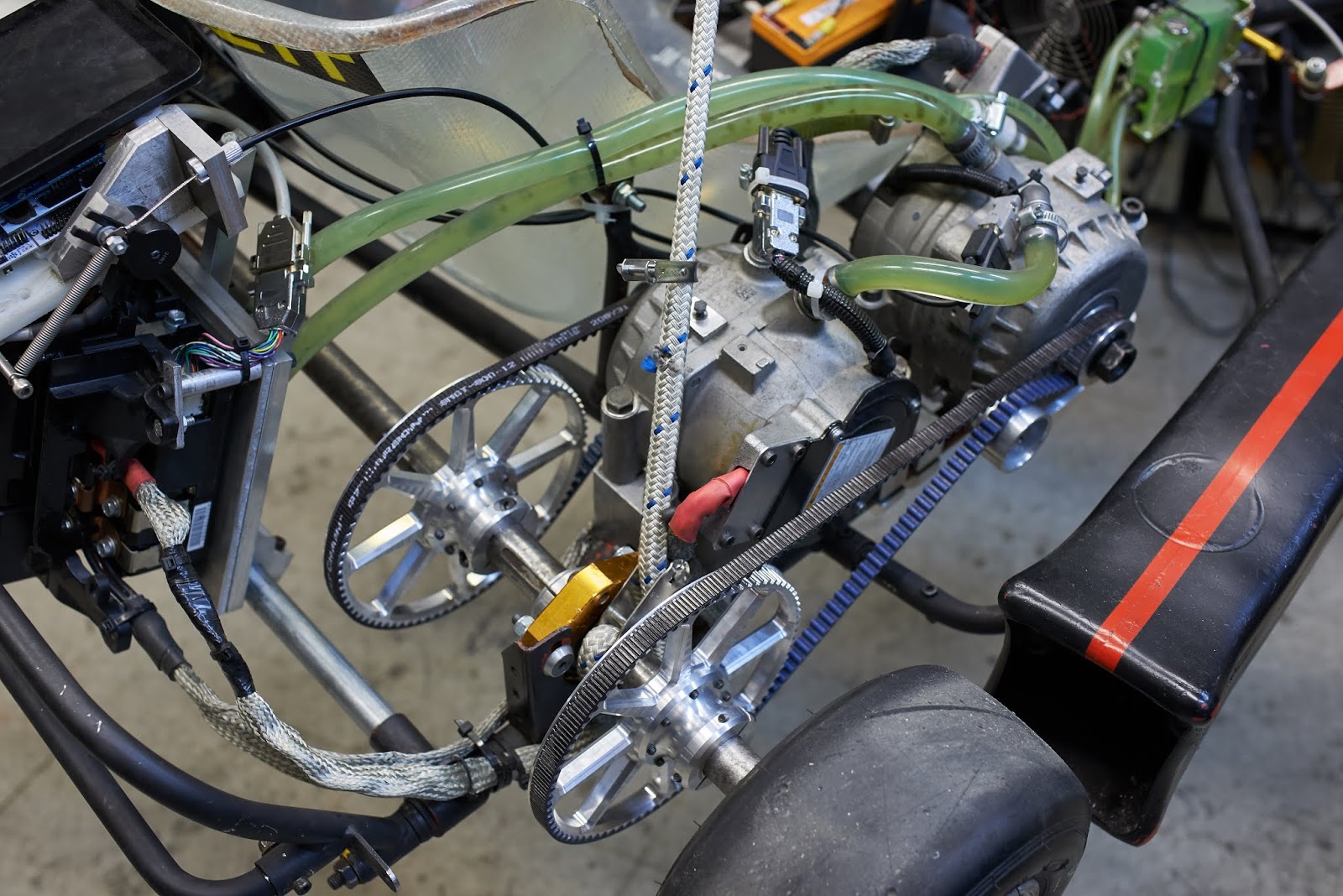
The motors are mounted via clamps to the frame and are watercooled using standard computer watercooling parts. Power transmission is done via Gates Polychain GT Carbon belts - we had originally used Gates Micro-V belts, but it was impossible to tension the very long outside belt. The Polychain Carbons are truly remarkable; they have about the same power handling capabilities as roller chain of the same width.


In the back is the big pile of electronics. Instead of an enclosure, the control boards are conformal coated, and the exposed HV busbar is covered in liquid electrical tape. This has done us remarkably well, even on grimy Cambridge roads. Logic is powered by a A123 12v7, which is good for about 4 hours of operation on a single charge (the converters inside the power module draw about an amp at 12V).


The rear disc brake is a generic 200mm Amazon moped brake. It is made of a terrible alloy that warps and discolors under heavy load, and generally doesn't seem to be suitable for anything. It stops the kart just fine though. In the future, a proper vented disc brake will probably be needed, especially at higher voltages and speeds.


The traction pack (42s LiPo) is made of 14 Admiral Pro 4000mAh in a 7S2P configuration. The Admiral Pro's have excellent performance when they work, but out of the original 18 we bought three have already failed - two had physically leaky cells and one has severely low capacity. The pack seems to work OK once the bad packs have been weeded out, but a 16% DOA rate is not really OK for what claims to be a premium battery.

The pack is mounted in the front to improve the weight balance of the kart. It compensates for the extra weight the inverter adds to the rear (~8kg); moving the traction pack from the side to the front greatly improved cornering performance, albeit at the additional risk of battery damage in case of an accident.


The front brakes are built out of moped calipers and some no-name discs we found in a drawer. Making the hubs and mounts was pretty straightforward; however, getting them plumbed in proved to be quite challenging.

Key specs are:
  • Motor: 2x Hyundai Sonata HSG, total 85 ft-lbs (115 Nm) @ 0-2,500 RPM, 40 HP (30 kW) @2,500-10,000 RPM on 160V nominal.
  • Traction pack: 42S 2P lithium polymer, total 168 V peak 8.0Ah.
  • Transmission: 4:1 (80t/20t) 15mm Gates Polychain GT Carbon.
  • Motor controller: custom field-oriented control; control stage: STM32F446RE, power stage: 2nd-gen Prius power module + capacitor. 

Friday, August 4, 2017

An interesting scope trace

Ch1 Voltage, Ch2 Current (20mV/A)

While debugging a laptop the other day I had a chance to throw a hall effect current probe on the DC input while it was running a game (NieR: Automata, just kind of chillin' around in the Resistance Camp). The trace is rather interesting - my interpretation is that there is that there some relatively low-power setup (the short dips to 6A on the cyan current trace), followed 8mS of lower-power GPU work (that has to be the GPU kicking in, the CPU (i7-4800MQ) can't possibly get close to 190W!), and 8mS of higher, but variable, GPU load.

Knowing Automata's rendering pipeline (which involves a lengthy, and costly, GI step), I would venture to say the 10A phase is the global lighting computation (which should, on a 200KHz current probe, appear to draw constant power), and the highly variable phase is generates the actual frame (the different power draws correspond to different stages and/or tricks involved in lighting the final image).

Hyundai Sonata Hybrid battery pack teardown


We (Ben, Charles, Dane, myself)  recently acquired a 2011 Hyundai Sonata battery pack to go with our Prius parts and Hyundai Sonata motors. The voltage (270V nominal) and capacity (1.4KWh) looked promising for medium-sized vehicles, the power capabilities were rather high (almost 60KW, according to INL), and the price was exceptional ($260 from LKQ for a 'B' grade one, $350 for an 'A' grade one).

Idaho National Laboratory had done some testing on the battery as part of the DOE AVTA program. The full report is here, but the gist of it is:
  • 72S 'Lithium Polymer' (3.75V nominal, 4.2V max)
  • 5.3Ah (1.4KWh) capacity
  • 400mohm pack resistance, ~5mohm per cell
  • 60KW peak source (at full charge, 40C), 46KW peak sink (at full empty, 30C)
  • 46KW average source (30C), 30KW average sink (20C)
5mohm on a 5.3Ah cell is not bad, on par with the best ("60C") R/C batteries on the market. The complete pack was rather heavy, but hopefully we could shed half or more of that weight by removing the steel armor. Without further ado, let's dig in!


The first thing everyone seems to notice: the enormous blower cooling the pack. Hyundai is very proud of its air-cooled pack design, and boy is that a mighty blower. I wasn't personally interested in the fan, but it could be useful for long-term traction duty.


Ignoring several ominous warnings and removing the HV safety cover, we are greeted by the contactor assembly (more on that later), and...


...the BMS! This one is interesting enough that we'll investigate more at the end of the post.

Moving on, lifting the main cover off the pack reveals the guts of the battery:


It's hard to tell from the photo, but the big silver bars (two on top, one underneath the modules) hold the pack in compression via the end-plates, which are padded with high-density foam.


The modules bear a 'GreenPower' label; there are several power companies going by that name, but none of them seem to make hybrid batteries.

Removing a few dozen screws and unplugging the balance connectors liberates the modules. Not shown: make sure to remove the safety disconnect before servicing the pack internals!


The modules are conveniently sized; each one is 8S/5.3Ah and weighs a hair over 2.5kg (2.6, to be exact). Sadly there is a whole lot of empty space in each module, presumably for airflow, and as a result energy density is quite poor.

Moving on to the contactor box, undoing a large number of plastic snaps reveals two adorable little 400VDC/80A contactors:


I have no idea how they get 35KW through an 80A contactor...

A Detour: the BMS

The BMS is remarkably straightforward inside - in fact, entirely made of off-the-shelf components.


The big IC is a microcontroller. The good news? It has a datasheet! The bad? It is some sort of godforsaken Infineon part, built on a custom uArch and costing $22

Come on guys, how hard is it to use an ARM?

The actual balancing assemblies are built around the LTC6802 stackable battery monitor. Each chip monitors its own module, resulting in nine chips daisy-chained into each other. 

Communication across the LV/HV isolation barrier happens via a pair of  Texas Instruments ISO7241C digital isolators, powered by a pair of 1W board-mount DC-DC converters made by Mornsun (I've never heard of them? Have you?). These seem to be clones of the popular CUI 1W modules.

The strange-looking package above the micro is an Infineon TLE6220 - some sort of SPI-controlled switch for controlling the precharge and main contactors.

THE VERDICT

The good:
  • Rather low ESR and high discharge ratings - 40C peak for 10s is about as good as anything gets.
  • Convenient packaging; modules are a reasonable voltage and capacity and constrain the prismatics to some extent, requiring only a simple external clamp to maintain compression.
  • BMS is built out of off-the-shelf components, giving some hope for reverse-engineering and/or reprogramming.
  • Very cheap; the equivalent pack from a Chinese hobby vendor would be well over a thousand dollars.
The bad:
  • Very poor energy density, a quarter that of a standard LiPo and half that of a bare A123 pack.
  • Can't reach 48V nominal using the modules.
Overall, not a pack for battlebots or flying things, but for weight-insensitive applications the price, power, and convenience pretty much can't be beat as of now (early 2017).

Saturday, March 4, 2017

Characterizing Ryzen R7 overclocking behavior

It's been a while since I made an overclocking post, mainly because nothing interesting has happened since Sandy Bridge. Ryzen has been the first new thing in half a decade to hit the market, so I dutifully went and bought a R7 1700 and an Asus PRIME B350-Plus in the name of science.

All tests were done using a 400W Antec server supply. CPU currents were measured using a clamp DC ammeter on the 12V wires going into the CPU 8-pin. The rest of the setup consisted of Windows 10 Enterprise (I made sure Defender and Windows Update were disabled), an XFX HD5750 for basic video output, and a 320GB 7200RPM 2.5" drive. Not the most upscale of setups, but unlikely to affect overclocking figures.Everything was done on an open-air setup in a room with ~20C ambient temperatures - I expect stock cooler mileage to go down slightly in a case with higher ambient temps. Adjustments were made on-the-fly in Ryzen Master.

Stock cooler numbers

Wraith Spire is remarkably good for a stock cooler, able to hold off 120W while remaining reasonably cool. Gone are the days of shitty stock coolers that would run stock-clocked i7's at 90C.

[​IMG]

The bad news: 3.8GHz seemed somewhat unattainable on the stock cooler; there was a distinct feeling of thermal runaway (Prime95 would run until temps hit about 76C or so and then crash, but not hard enough to bring down Windows).

[​IMG]

Power seems quite in check out to 3.7GHz, though you do lose some efficiency past 3.5GHz. 4.0GHz is clearly out of the comfort zone for this sample - the jump from 3.8 to 4.0GHz is huge.

High-end air numbers

I broke out the old Thermalright TRUE 120 for some testing; it's not a modern cooler by any means but it could cool 200+W 45nm processors back in the day so I figured it would be fine. Note that numbers up to 37x are the stock cooler numbers from above, the stock cooler did a good enough job that I didn't bother rerunning the benchmarks.

[​IMG]

40x was pretty unattainable on my setup. Temperatures climbed rapidly, eventually crashing hard enough to trigger a reboot. I'm pretty sure this is a die thermal resistance limit; it is just not possible to remove 25W per core on Ryzen's die while maintaining the sub-70C temps needed for stability. I tried 1.4375V as well, but power climbed to 204W (17A) and the system similarly rebooted.

4C/8T numbers

Going by the theory that the frequency wall at 39x was thermal, I disabled four cores in hopes that the lateral heat conduction in the die would reduce temperatures substantially.

[​IMG]
While temperatures did go down dramatically, enabling much improved operation at 40x, 41x was very out of reach; temperatures remained in control, but Windows crashed before I could get meaningful power readings.

Prime95 "blend" numbers

Not satisfied with the lack of 4GHz, and still going by the thermal stability theory, I tried Blend, which I figured is more representative of enthusiast thermal loads.

[​IMG]


It pulled off 40x fine, albeit requiring slightly more voltage to do so than the quad core test (crash after about 10 minutes of blending at 1.375V) As a bonus, the lower temps also translate into slightly reduced voltage requirements.

Voltage/power scaling

For science's sake, I left the multiplier at 30x and slowly raised the voltage.

[​IMG]
Not as interesting as I expected, looks like standard quadratic-ish scaling out to 1300mV, then something happens, resulting in a bump in power consumption. The bump is looks like part of the reason we can't get past 40x; if process refinements could move it out we'd get higher clocks.

Conclusions
  • Ryzen Master is pretty good. After leaving it running for half an hour while I wrote up this post it crashed, but seemed to work fine when I reopened it. The UI is damn responsive for a overclocking tool, as good as any I've ever used.
  • The PRIME B350-Plus BIOS is not great as far as overclocking goes. In particular, the option to set a fixed voltage is missing, and I have no idea what the 'FID' and 'DID' ratios do (raising DID seems to lower the target frequency??). Presumably this will be remedied in a later BIOS release.
  • Ryzen, or at least my sample, seems to have poor frequency-temperature characteristics past about 75C. On both the 38x stock and 40x aftermarket tests, Windows crashed when the temperature readout in Ryzen Master crossed 75C.
  • It looks like on 8 cores, the thermal limitations come from the ability to pull heat out of the die, not because of the thermal resistance of the heatsink to air. Temperatures climbed rapidly in response to frequency changes, and at least qualitatively, the fins on the TRUE 120 were quite cold.
  • On 4 cores, efficiency is solid. Voltage scaling is not as good as Kaby Lake (which ships at 4.2GHz and typically in the 1.225V neighborhood), but power consumption is in control and temperatures are very low.
  • Ryzen has two distinct bumps in efficiency. I'm wary of saying where they are based on a single sample, but it looks like the first is in the neighborhood of 35x and the second, around 38x. Pushing for that last two bins (or eight, if you want to be picky) causes an insane increase in power consumption on my sample; the sample to sample cutoff may vary but I feel safe in saying that you will lose a whole lot of performance/watt right around 3.8+/- GHz.