Schmidt-Cassegrain Telescopes (SCT's) are incredibly cheap on the secondhand market - 8" OTA's are around $350, 10" (Meade)/11" (Celestron) OTA's under $1000, and even the mighty C14 can be had for under $2000 on good day. Compared to, say, an Ritchey-Chretien telescope (a Cassegrain with a hyperbolic primary) this is an incredible deal - a generic 10" GSO RC sells for about $2500 new and is rarely available on the used market. These low prices are largely due to decades of experience in mass production combined with huge volumes for the visual market.
Unfortunately, if you're interested in photographic rather than visual use, SCT's have traditionally been a questionable choice. SCT's are only corrected on-axis; off axis, they suffer from both coma and field curvature - very severe field curvature at that, thanks to the folded design. Now, RC's (and their relative, the Meade ACF telescopes) are really not that better - they are coma-free, but they replace coma with severe astigmatism and still suffer from field curvature.
Despite the generally poor reputation, the SCT design has a key merit - it uses spherical mirrors. A spherical mirror with a stop placed at the center of curvature has just two aberrations: spherical and coma. This is because the mirror "looks the same" from the point of view of every field angle, so all of the asymmetric aberrations are inherently absent. The Schmidt corrector on an SCT corrects for spherical aberration, which means the only remaining aberration is field curvature, right?
Obviously not, because SCT's are full of coma. This is because the corrector (stop) on a commercial SCT is intentionally moved closer than one radius to the primary in order to shorten the overall length of the system and improve handling. This results in performance like so:
Performance is poor - at the corners of a full-frame field (21mm, about 1 degree), RMS spot sizes reach 108 microns, and this system has virtually no contrast past 10LP/mm (Nyquist for 25um pixels) in the corners.
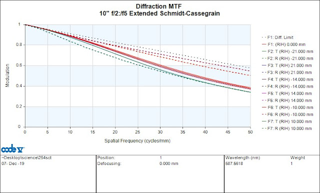
However, let's move the corrector out to ~660mm from the primary, and add a single concave lens. Performance now looks like this:
Performance is pretty decent, with 21 micron RMS spots in the corners at best average focus, greatly reduced coma, and good contrast even at 50 lp/mm.
The weakly diverging lens (130mm radius of curvature, e.g. Newport KPC067) in front of the image plane serves to cancel out the inherent field curvature of the system and substantially improves performance. It also extends the focal length slightly (from 2500mm to 3000mm), which is not great unless your camera has a KAF-1001E or similar large-pixel sensor. It has the additional disadvantage of adding some chromatic aberration, as it is a singlet with nonzero net optical power - for one-shot color imaging it might be best to just leave it out and accept the field curvature. For narrowband (or even LRGB) imaging, just refocus for each wavelength and it should work fine.
The verdict: yes, it does work. The only other option for correcting an SCT is the Starizona SCT corrector, which is a great product; however, at $599 for the full-frame version it only makes sense on one of the larger instruments. This scheme is obviously more labor intensive - actually implementing it is closer to "build a new telescope using the glass from a commercial SCT" than "modifying a commercially available telescope". Your best bet if you actually build this would be a secondhand C8 ($300), a Chinese focuser ($100) and an a7S ($600 used), a combination which gives a well-corrected ~1 degree field of view.
Saturday, December 7, 2019
Wednesday, March 6, 2019
Freefly Systems ARC200 teardown
Most motor controllers are bad. They range from not really doing motor control (any hobby controller, eBike controllers) to being electrically questionable (small VESCs) or having flaky (SimonK and BLHeli, which in addition, don't do real motor control) or confusing (Sevcon) firmware, to being mechanically questionable (most 'servo drives').
On the surface, the ARC200 doesn't really distinguish itself; nominally, a '200A 48V inverter with FOC' isn't much different from any of the large VESC variants out there. However, none of the big VESCs are great (questionable layout, too much electrolytic capacitance, terrible connector choices, too expensive), and the ARC200 sits at a comfortable price point above the bad Chinese controllers but well below the VESCs and industrial servo drives. In addition, I am good friends with several engineers at Freefly, and had high hopes that their involvement in the product would make it not bad.
What Makes a Motor Controller?
When most people evaluate a motor controller, they immediately jump to the power stage. However, the power stage is but a small part of the system, and with power MOSFETs getting cheaper and better, device selection and layout are becoming less and less critical.
All DC-operated inverters share the following equally important building blocks:
Microcontroller and firmware: You can't really screw up the implementation of a microprocessor, but boy is it possible to screw up an implementation of FOC. The core algorithms are probably right (you quickly notice swapped variables or extra factors of -1), but managing the rest of the state machine is much harder. Startup conditions, integral windup, throttle bounds, and interrupt priority are a few of the many ways to go wrong. The firmware is probably the hardest to test, as some edge operating conditions are difficult to trigger on the bench.
On the other hand, writing good motor control firmware is no different from writing any other kind of software, but most hardware engineers (and many software engineers!) don't have formal training in writing robust code.
Low voltage power supply (LVPS): The LVPS is a DC-DC converter that takes the DC link voltage and generates the 12-15V and 3.3-5V rails to power the gate drive and logic, respectively. The LVPS is a somewhat tricky part to design; typically, it is built using an off-the-shelf SMPS controller IC. Commercial SMPS controllers are "black boxes" that usually expect relatively clean DC input and a slow load. Inverter applications, in contrast, are very noisy, since the DC link is full of transients from the power stage. Cheaper or very low-voltage controllers will usually run the logic off a LDO, possibly with a resistor in series. This suffers from a similar problem; in fact, an unfiltered LDO is guaranteed to pass input transients to the output, as no linear regulator is capable of handling sub-microsecond input changes.
LVPS failures will usually take out the entire inverter, since the failing logic and gate drive rails will put the entire control stage in an invalid state for several milliseconds, leading to desaturation or shoot-through of the power stage. In addition, failure of the LVPS to regulate (due to an input transient) will often damage the control stage by passing the transient to the output.
Isolation and gate drive: The gate drivers turn the power MOSFETs on and off. There are various levels of sophistication; the dumbest gate drivers are just a pair of complementary BJTs, the smartest ones integrate capacitive isolation, desat detection, and fault signaling. Closely related is how the gate drives are powered. Most low-voltage controllers power all six off a single 12 or 15V rail, and use bootstrap capacitors and diodes to generate the high-side voltages. This adds the obvious benefit of simplicity, but makes layout a little tricky (the 12V rail has to fan out to all six gate drives) and has the rather large disadvantage of connecting the logic and power grounds. Circulating ground currents can then potentially upset the microcontroller and LVPS.
In contrast, high voltage inverters always fully isolate the gate drives, for safety reasons. This has the neat benefit of completely separating the control and power grounds (indeed, most 300V+ controllers require a separate low voltage power supply as input), but adds a ton of complexity.
I/O: Control inputs are dangerous, because they often run over a long wire. Small controllers rarely isolate their inputs, which means analog and serial control cables contain a wire directly connected to the ground of the microcontroller. Needless to say, attaching a large antenna to logic ground and having it pick up every switching transient in the system often leads to poor performance.
Industrial servo drives almost universally have optically isolated inputs. In this case, the control signal drives the LED in an optoisolator, removing the need to bring logic ground out of the controller. Annoyingly, most hobby controllers marketed as 'opto' don't actually have optoisolated inputs; 'opto' in this case only means that the controller does not provide a 5V accessory power supply.
Power stage: And now, we finally get to the power stage. The choice of power device is practically a non-issue in this day and age, but layout still requires some consideration, especially in small controllers (where cost and compactness considerations sometimes lead to electrical compromises). In particular, very high-current, low-voltage controllers have trouble finding space for enough copper to carry the full phase current, and sometimes run into package current limitations as well.
Surprisingly enough, high-voltage inverters are much easier to lay out. The smaller ones (400V, up to ~50A) are covered by fully integrated 'smart power modules', and the larger ones (up to ~300A) are covered by sixpack IGBT modules (which contain 3 half bridges sharing a DC link, but no gate drive).
Selecting capacitors is also somewhat of a black art. Electrolytic capacitors are mostly resistors at high frequencies, and a poor implementation of an electrolytic DC link capacitor can be worse than nothing (the energy stored helps blow up the devices in case of a failure). On the other hand, insufficient DC link capacitance leads to high ripple current in the DC link cables (which could be long, and therefore potential sources of EMI) and high voltage transients (switching spikes aside, the average DC link voltage + half the peak to peak ripple needs to remain under the voltage rating of the devices). For large high-voltage inverters, the cost and weight of the capacitors is often equal to that of the switching devices.
Electromechanical components: Connector selection is a matter of taste and application. The automotive and aerospace industries have stringent isolation, water-resistance, and even coloration requirements. An inverter for an OEM robotics application might value weight and compactness over waterproofing, and an industrial controller would use common connectors found in automation. There are clear wrong choices (pin headers come to mind), but never a single "best" connector. The same goes for housings and thermal management.
The Actual Teardown
Phew, that was a lot of intro. This teardown has an associated Flickr album containing high-res images, because nothing sucks more than not being able to see the part number on an IC. For convenience, some of the images will be reproduced here, but are limited to Blogger's 1600x1200 resolution.
Overview, Microcontroller, and LVPS
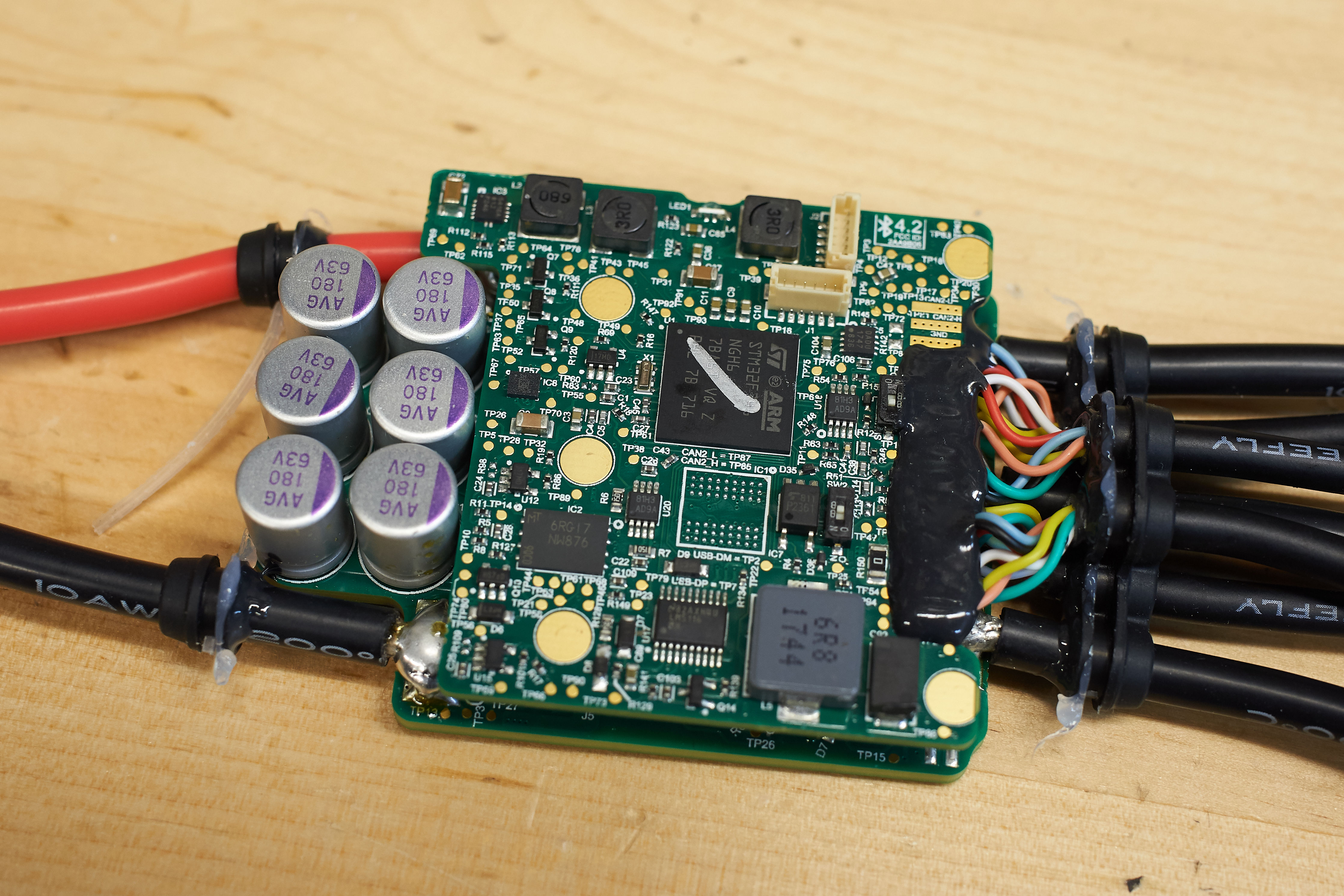
The ARC200 is constructed as a two-board stack; the top board contains the LVPS, microcontroller, and additional logic, and the bottom board carries the power devices, gate drive, and capacitors.
The microprocessor is an STM32F746NGH6, which is a serious part that costs almost $12 in quantity. For better or for worse, this is the largest microcontroller I have seen in a motor control application (it beats out the F446RE in my own designs). In addition, the microcontroller is connected to a 512MB SPI Flash, so there is plenty of room for expansion and future features if so desired. The main logic rail is generated by a LM5116, which is a 100V-capable buck controller IC.
Visible towards the right (near the I/O connectors) are a MCP2562 CAN transceiver, a LMV612 dual op-amp, and a TLP2361 dual optocoupler. The CAN transceiver's purpose is obvious (though it is worth noting CAN is not included in the available external interfaces), the LMV612 probably serves to buffer analog throttle and the TLP2361 probably buffers various forms of digital throttle. Also visible are some small DIP switches, which probably shouldn't be flipped.
Additional Logic
The backside of the logic board reveals several additional components. A number of LMV612's likely provide additional analog functionality. To the left, a TPS542941 buck regulator generates the 5 and 3.3 V rails, augmented by a healthy number of ceramic capacitors. To the right, the capacitors and MOSFETs (low side, high side) for the LVPS are visible - the LM5116 does not integrate switches. A diode likely provides reverse polarity protection. On the upper right, there is an ST M24128 - a somewhat strange choice given the amount of FLASH available on the F7, but perhaps it saves flash wear?
On the bottom left, a tiny Rigado BMD-350 provides BLE connectivity. This is a trick to avoid having to FCC certify the 2.4GHz part of the controller, as well as making layout easier (implementing RF SoC's can be tricky).
Also visible all around the board are the short board stacking headers that connect the logic deck to the bottom board.
Gate Drives
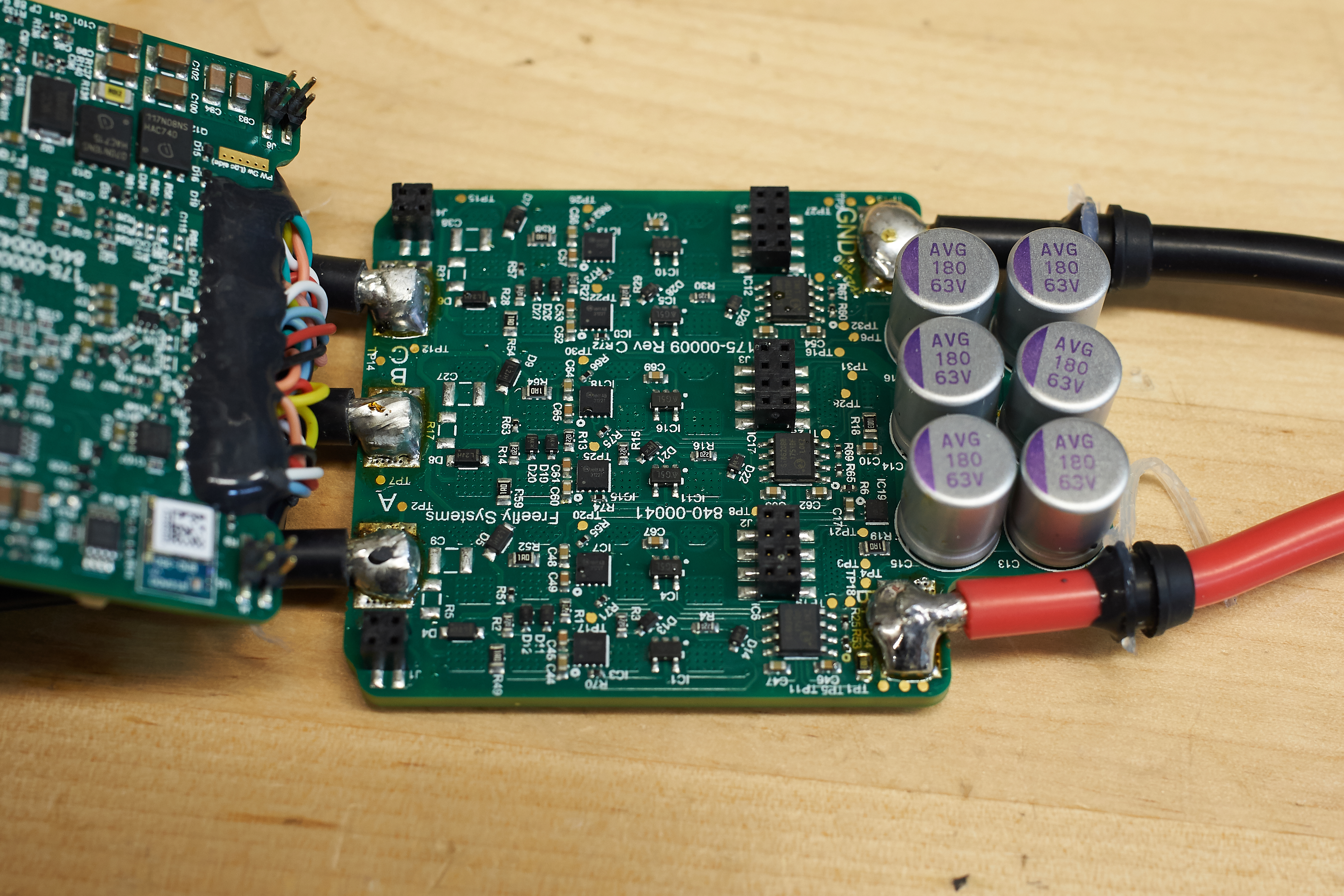
The gate drive uses a standard bootstrapped design with some twists. Because level-shifted gate drive IC's top out at 4A (and even those are somewhat fragile) and fully isolated drives are very expensive, the gate drive stage uses FAN3122 9A discrete drivers, bootstrap diodes, and Silabs SI8620BB digital isolators. In addition to providing high-side control, the isolators serve to somewhat protect the microcontroller from transients in the power stage. A column of tiny linear regulators powers the isolators.
A number of diodes provide various functionalities including bootstrapping, turn-on/turn-off time separation, and gate protection.
Also visible here are the DC link capacitors, six 180uF 63V parts. The lack of ceramic capacitors is disappointing, but realistically, at the RMS currents the ARC200 targets, 100V/200uF of ceramics would have been required, an expensive proposition at any time and especially now during the ceramic capacitor shortage.
Power Stage
The power stage uses four TPH2R608NH devices per switch. These are very economically priced parts, only 67 cents in full reel quantity for a 75V 2 mohm FET with reasonable gate charge. In fact, they are cheap enough that to the right, three more of them are used to provide anti-spark functionality. Current sensing is done with three (!?) huge 250uohm shunts. Appearances are deceiving; the SOIC device next to each shunt is not a shunt amplifier, but rather another SI8620BB. Instead, current sense amplification is likely implemented using several of the many LMV612's on the logic deck.
Mechanical Design
Additional Commentary
This is a pretty good controller. The logic stage is intense, featuring three buck converters, SPI flash memory, and possibly the largest microcontroller I have ever encountered in a motor control application. Freefly's implementation of sensorless FOC is class-leading, and the computing power of the F7 leaves room for potential new algorithms (such as HFI for salient motors). I generally don't believe in sensorless control (magnetic encoders are cheap and easy), but that kind of feature is perhaps relevant at this level. The LVPS is nothing particularly exciting, but the LM5116 is a good chip and the switching devices used in the buck converter are beefy to the point of being excessive.
The gate drive stage seems solid but perhaps a bit unusual, as it utilizes bootstrapped discrete drivers in combination with external RF-based isolators. I would like to do a further analysis for the circuit at some point, as some aspects are not immediately clear (for example, there appear to be six dual-channel isolators for six drivers, and VDD2 on the isolators appears to come from the bootstrapped supply).
The power stage is very solid - the switches use four 2 mohm devices each for a total resistance of 500 uohms per FET. This is much less than the resistance of the motor and at this level, switching losses are a huge part of the total losses, meaning adding more FETs doesn't necessarily improve performance by much.
For the price, I would have liked to see more isolation - it seems possible to build a 5-channel isolated supply for around $10 in 1ku. A fully isolated design is not inherently superior at 48V, but it greatly eases integration if there are multiple inverters in the system. That being said, testing the isolated supply poses its own challenges; at that point, the LVPS approaches the rest of the inverter in complexity. I would also have liked to see an all-ceramic DC link capacitor, but I don't know how that would have affected the retail cost of the controller - a ceramic capacitor suitable for 140Arms operation might very well be an incredibly expensive object.
Thursday, January 24, 2019
'unitepower.com' 48V 1800W brushless motor teardown
A friend recently acquired a '1800W 48V' brushless scooter motor and I decided to have a look inside, ostensibly for the purpose of doing thermal testing.
The rotor measures 63mm (diameter) by 73mm (stack height). This gives an air-gap-area*radius metric of 289 cm^3, which is not too shabby; for comparison, the Sonata HSG, which is a 60Nm motor, is 415 cm^3. The laminations are about .56mm thick, which is not great for high speed performance and is probably a huge reason why these motors are not very efficient.
The stator is surprisingly well-made. The fill factor is OK, and the concentrated windings mean there aren't a ton of end-turn copper losses. The stator also has a pretty high iron-to-copper ratio, which is good for peak torque and not good for efficiency. The large volume of iron in the stator is probably another contributor to the high losses - at peak efficiency, copper losses are less than half of the total losses.
The motor has hall sensors, installed using the standard in-the-slots technique:
The housing is mediocre. The end caps are cast aluminum, and the stator is pressed into a piece of steel tube, which adds quite a bit of weight. The motor is also much longer than it needs to be - out of the 177mm of total length, only 72mm contribute to torque production.
Motor specifications:
Type: Surface PM machine
Pole Pairs: 3
Resistance (line-to-line): 73 mOhms
Inductance (line-to-line): .415 mH
Flux linkage [derived]: 0.036 Vs
Back EMF:
Full of harmonics, but reasonably sinusoidal.
Thermal testing:
Thermal testing was done by passing DC current through a pair of phases while watching the temperature of the end turns with a Flir A65 thermal camera. We initially set a temperature cutoff of 110C, but backed down to 95C after noticing some degradation in the either the enamel or epoxy in the stator at around 100C (this is pretty terrible; good wire can operate at 200C!).
Performance with no additional cooling proved to be rather poor; at 28A (which is the RMS current at 40 peak phase amps), the stator hit 95C and started overheating.
Performance with active cooling (a Sunon PMB1297PYBX-AY 12V blower) proved to be much better; we were able to achieve 33Arms (46 peak amps) with a stator temperature that stabilized at around 90C.
Note that this is a best-case operating scenario; at stall, there are no iron losses. Further testing at speed is planned for a later date.
Conclusion:
This is "a lot of motor" - it can produce huge amounts of peak torque. Unfortunately, terrible efficiency, non-existent high-speed performance, and a dubiously low temperature cutoff all serve to severely limit its applications. Even for its advertised application (small electric scooters) it is a poor choice, as 70% peak efficiency means around 20% of the battery pack is wasted (versus a 90% efficient machine).
These motors are very close to being good - better wire and thinner laminations, both of which wouldn't drastically increase costs, would go a long way to making them more useful. Maybe in the future, we will see an updated version with these improvements, but for now, I would steer away from these motors.
Wednesday, January 9, 2019
Feiyu Tech A1000 Gimbal Teardown
The Feiyu Tech A1000 is a midsize handheld gimbal for compact cameras and small mirrorless cameras. I recently acquired one and took a look inside, with the ultimate goal of operating the gimbal without the handle, which contains the batteries and some electronics.
The gimbal consists of a "main unit", which is attached to a handle by the means of a threaded collar. The handle contains the controls for the gimbal, as well as the batteries; it is not possible by default to turn the gimbal on without the handle.
The first task was to disassemble the handle. My hunch was that the handle suppled 7.4V (2S Li-Ion) to the inverters in the main unit, and sent pan and tilt commands via serial to a microcontroller in the main unit that ran the stabilization loop and talked to the inverters and IMU via I2C.
The Feiyu gimbals are remarkably easy to take apart - everything was held together with screws with not a plastic snap in sight. Removing the four Phillips screws from the top of the handle released the connector board:
The contacts for the spring-pins on the main unit are just pads on a matte black (!) PCB; the top board is just connectors with no active components.
Removing the four socket cap screws on the side of the handle reveals the bulk of the circuitry:
The module is an NRF51822 carrier module...with some sort of bonus wire on it to act as an antenna. Completely not OK - the reason manufacturers use carriers is to avoid having to undergo additional FCC certification, and adding the extra antenna defeats this. The chip below it (next to the USB port) is a Silabs USB to UART bridge. This is a notable difference from the smaller Feiyu gimbals, which put the UART bridge inside the USB adapter and run serial over the physical USB connector.
The backside isn't too exciting - a buck converter provides power for the electronics on the board (and possibly logic power for the inverters as well). The connectors are all neatly labeled, a nice touch.
Moving on to the inverters (we look inside one motor, but the other three are nearly identical):
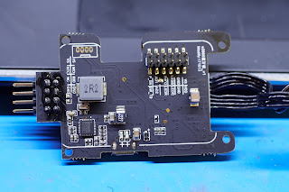
The microprocessor is an STM32F303, an popular choice for gimbals. Two shunts are present - no cost-cutting one-shunt techniques were used here.
The power stage is an MPS6536 integrated brushless driver IC. The position sensor is not on the board; presumably, it is on the other side of the motor.
The connector board on the main unit reveals something surprising: unpopulated pads for a NRF51822 module are present.
Presumably at some point during development, a handle-less version was in fact planned, but was aborted before it reached full production.
Some further analysis:
The handle does have an microcontroller in it - it is possible but unlikely that the NRF51822 (which contains a Cortex-M0) is used for the stabilization loop. However, the only data lines running up into the main unit carry 115200 baud serial on them; standard async serial is not easily daisy-chained, and very few IMU's speak UART. Most likely, one of the inverter microcontrollers also does stabilization (this is the case on the Feiyu Tech wearable gimbals, which have no handle).
The gimbal consists of a "main unit", which is attached to a handle by the means of a threaded collar. The handle contains the controls for the gimbal, as well as the batteries; it is not possible by default to turn the gimbal on without the handle.
The first task was to disassemble the handle. My hunch was that the handle suppled 7.4V (2S Li-Ion) to the inverters in the main unit, and sent pan and tilt commands via serial to a microcontroller in the main unit that ran the stabilization loop and talked to the inverters and IMU via I2C.
The Feiyu gimbals are remarkably easy to take apart - everything was held together with screws with not a plastic snap in sight. Removing the four Phillips screws from the top of the handle released the connector board:
The contacts for the spring-pins on the main unit are just pads on a matte black (!) PCB; the top board is just connectors with no active components.
Removing the four socket cap screws on the side of the handle reveals the bulk of the circuitry:
The backside isn't too exciting - a buck converter provides power for the electronics on the board (and possibly logic power for the inverters as well). The connectors are all neatly labeled, a nice touch.
Moving on to the inverters (we look inside one motor, but the other three are nearly identical):
The microprocessor is an STM32F303, an popular choice for gimbals. Two shunts are present - no cost-cutting one-shunt techniques were used here.
The power stage is an MPS6536 integrated brushless driver IC. The position sensor is not on the board; presumably, it is on the other side of the motor.
The connector board on the main unit reveals something surprising: unpopulated pads for a NRF51822 module are present.
Presumably at some point during development, a handle-less version was in fact planned, but was aborted before it reached full production.
Some further analysis:
The handle does have an microcontroller in it - it is possible but unlikely that the NRF51822 (which contains a Cortex-M0) is used for the stabilization loop. However, the only data lines running up into the main unit carry 115200 baud serial on them; standard async serial is not easily daisy-chained, and very few IMU's speak UART. Most likely, one of the inverter microcontrollers also does stabilization (this is the case on the Feiyu Tech wearable gimbals, which have no handle).
Subscribe to:
Comments (Atom)


