Thursday, December 13, 2018

Tiny Camera on a Big Lens


With the release of the Nikon Z6 and Z7, Nikon shooters at long last have a way to add stabilization to unstabilized lenses. This presents some nifty opportunities - a decade's worth of fast AF-S primes are now all stabilized, and some very desirable zooms such as the 14-24 and the Sigma 24-35 ART also gain stabilization.

Much more interestingly, the original AF-S supertelephotos all gain stabilization. The VR versions command a $2000 premium over their unstabilized counterparts, so clearly there are substantial (one Z6 per lens!) savings to be had here. The situation is not as magical as it first seems though - small angular motions transform into huge shifts at the sensor, so in-body stabilization is not as effective for long lenses as lens-based stabilization.

I don't have a Z-series camera, but I do own an A7ii (which has a very similar sensor resolution and stabilization system) and an AF-S 500mm f4, and had been contemplating a Z6, so I was interested in testing the effectiveness of IBIS when used with really long lenses.

Testing stabilization is a little tricky, because there is inherently a human factor involved (some people are really good at keeping cameras stable, some less so). For these tests, I settled on a compromise which I felt would be representative of my shooting situations:

  • Lens and camera mounted on a gimbal head on a tripod - I think a setup like this will always have some kind of support underneath it, be it tripod or monopod; other than maybe the 500FL no one is going to be handholding a big supertelephoto prime for very long.
  • Gimbal head locks loosened - if I'm shooting with a long lens, I'm probably also following something that moves. Realistically, the scenario in this test would only show up for slow-moving wildlife or portraiture; any real "action" will require 1/500 or faster anyway to stop subject motion.
  • Camera triggered by pressing shutter button - in the same line of reasoning as above, I wanted to be able to keep my hand on the grip at all times.

Results

Blogger is not really set up for hosting huge images, so the test results are externally hosted here. 100.png, 200.png, 400.png, and 800.png are, respectively, 1/100, 1/200, 1/400, and 1/800 shutter speeds without stabilization; is100.png, is200.png, is400.png, and is800.png are the same speeds with stabilization.

Analysis

IBIS is effective, even for very long focal lengths. At 1/100 for example, the worst frame (out of 4) with IS off looked like this:


Completely unusable, by most standards. In contrast, the worst frame with IS on looked like this:


Still a bit soft, but this would be usable for smaller output sizes, especially with some careful postprocessing.

Stabilization also helps, but much less visibly, at 1/200:

Off:


On:


However, stabilization is not magic. While the 1/100 shots with IS on are usable, they are still not quite as sharp as a 1/800 image:


The 1/200 shots get pretty close, but are still a bit blurrier (the difference would likely not be perceptible with a softer lens).

Conclusion:

What did we learn? Well, it seems for at least one shooting scenario (lens supported but not completely locked down), IBIS does make a difference, allowing for at least 2 stops of stabilization. Anecdotally at least, this puts it on par with lens-based stabilization. It's a little hard to tell - lens-based stabilization is supposed to be good for 3+ stops, but there's precious little subject matter which needs a big telephoto prime and moves slowly enough to be shot at 1/30.

We also learned that fast shutter speeds are necessary to extract maximum performance from a telephoto prime. While sensor-based stabilization allows for usable shots at slow shutter speeds, reliably achieving the maximum optical performance of the lens still requires 1/(focal length) or shorter exposures.

The other question is how much more stable the viewfinder image is with IBIS. There are some scenarios where it is possible to shoot handheld, at least for a little while, and having IS is quite useful for framing purposes. Unfortunately, this is much harder to test, and I expect the answer to be quite negative, given how much the viewfinder image moves.

Sunday, July 29, 2018

Field Weakening, Part 2

Recall in a previous post we had found an analytic solution to the field weakening problem. Unfortunately, the model is useless in practice; high currents (which are needed to cancel large amounts of PM flux) result in much lower inductances (which serves to decrease the amount of flux being canceled), resulting in numbers which are implausible and wrong.

However, while back EMF depends on the inductances, flux linkage, currents, and speed, torque is independent of speed - the same \((I_d, I_q)\) will always produce the same torque, no matter what speed the motor is at. Furthermore, we already know the relationship between torque and the axis currents from stall testing, and we can used this data as a black box to look up torque outputs from \(I_d\) and \(I_q\) inputs.

We are going to make an additional huge assumption: at high speeds, the current is low. This is not necessarily true, but for motors designed to be aggressively field weakened, the achievable current is likely low due to the high inductances. This assumptions means we can use the voltage equations to compute the back EMF for most of the field weakened operating regime. Of course, there will be a transition around base speed where this assumption doesn't hold, but we can "fix that in post".

Armed with this, we can write a simple C++ program (source, executable, sample input) to search the entire space of \(I_d\) and \(I_q\) values. The program is not particularly good or fast, but the brute-force approach makes it very robust and trivially extensible to a saturated motor (just override the Vs2() function in the MotorModel class with a lookup table based one). In contrast, Newton's-method based approaches seem to fail if the voltage surface is too complex.

The program generates some very reasonable output; for example, the following plot of power and torque versus speed for the HSG at 160V:


The flat part of the torque-speed curve extends up to what would traditionally be called "base speed" [1]. A surface PM machine spends most of its time operating in this regime, as operating over base speed results in reduced power output and efficiency. In contrast, an IPM is a constant-power device past base speed; this has several implications for system design:

Hybrid vehicles: Field weakening is very important for hybrid vehicles.  Consumer hybrids have electric subsystems optimized for city driving. In order to optimize efficiency in this scenario, it is beneficial to have a high reduction between the motor and the wheels, to reduce the motor current required to accelerate the car. This typically means putting base speed somewhere around 40 mph, which means at highway speeds, the motor is operating well beyond base speed. Being able to produce power at these speeds is important for consistent performance.

There is also a class of emerging high-performance hybrids. Typically, these use a combination of one or two motors, a medium sized (around 5KWh) battery pack, and a very high power forced-induction internal combustion engine. The electric subsystem is used to compensate for the narrow power band of the ICE by adding additional low-speed torque. It also usually provides power to all four wheels, improving handling and launch performance. Finally, it improves the regulatory status of such cars by at least nominally increasing the fuel economy. Once again, we find it beneficial to place base speed at a relatively low speed in order to maximize the launch torque delivered to the wheels (and reduce the weight of motor required to deliver that torque to the wheels); consequently, field weakening is needed to prevent the top speed of the car from being voltage-limited.

Pure electric vehicles: It is widely known that most EV's have a single-speed gearbox. This is entirely due to the power-speed profile of an IPM [2]; as the motor can reach peak power at very low speeds, a variable-speed transmission is not necessary to maximize power output across the entire operating range of the vehicle.

In fact, we can simulate the broad power band of an IPM with a surface PM machine and a continuously-variable transmission. It is usually not desirable to do so [3]; multi-speed transmissions incur additional complexity, weight, cost, and losses, usually negating the improved torque density of the surface PM motor. The only cars that use surface PM motors (Honda, Hyundai) are hybrids which are strongly derived from existing gas-only cars and already have manual transmissions.

Combat robots [4]: Spinner weapons are very similar to cars - both are inertial loads that have highly variable speed profiles. Interior PM machines have obvious mechanical benefits, as the rotors are much more robust. In addition, having a virtually unlimited top speed makes match-ups more consistent. Having moderate weapon speeds is usually beneficial, as it improves energy transfer and tooth engagement. However, in the vertical-on-vertical matchup (which is becoming much more common), the robot with the higher blade speed hits first. In this case, being able achieve very high speeds can greatly improve chances of victory.

And of course, higher-speed weapons hit harder if they do engage, so having the option to spin up to very high energies can be beneficial in certain situations.

Notes

[1] Technically, base speed also depends on stator current, so the correct terminology would be 'the base speed of the motor is 2000 rpm at 180A'.

[2] Induction machines (Tesla) and synchronous reluctance motors (no one yet) have similar characteristics, and trade off torque density for reduced cost.

[3] There are some designs which use a 2-speed transmission to further improve efficiency below base speed.

[4] No one has done this yet, but someone should!

Saturday, July 28, 2018

IPM's: an overview


The brushless motors we typically see on the mass market are "surface PM" machines. In this configuration, the permanent magnets (PM's) are glued to the surface of a steel rotor. Torque is generated by rotating the magnetic field in the stator electronically, which in effect continuously "pulls" the PM's on the rotor towards the coils on the stator.


In contrast, all automotive PM motors are "interior PM" machines. This means the magnets are buried inside a steel rotor. While this seems counter-intuitive at first (doing this moves the magnets further from the stator and makes the rotor heavier), putting the magnets inside a chunk of steel gives the motor several features which are highly beneficial for traction applications.

Greatly increased inductance: The surface PM motor has low inductance. This is because the PM's have a much lower permeability than steel, effectively putting a huge air gap in the flux path. In contrast, the interior PM machine places the rotor steel very close to the stator teeth; the magnetic air gap is only the size of the physical air gap, and this greatly increases the inductance, often by a factor of 10 over a similarly-sized surface PM machine.

Having high inductance is important, because for traction applications, the switching frequency is primarily determined by the allowable current ripple (excessive current ripple increases the resistive losses in the copper and conduction and switching losses in the inverter). Being able to reduce the switching frequency can drastically reduce inverter losses. Conversely, for some types of very low inductance and resistance motors (Emrax, Yasa), system efficiency is much lower than what the motor specifications alone would indicate, as Si IGBT inverters have a hard time efficiently driving these types of motor.

Position varying inductance: Why does this matter? Recall that inductance stores energy, and torque is the angle derivative of the co-energy of a system (or, roughly speaking, the system will try to settle to its lowest energy state). This means that by properly manipulating the stator currents, we can use this varying inductance to generate torque: the so-called reluctance torque. Reluctance torque is beneficial because it behaves very differently from the torque generated by the attraction of the magnets to the stator (the PM torque); it grows with both d and q-axis current, and doesn't necessarily generate additional back EMF.

We typically assume that the inductances vary sinusoidally; the typical model therefore has two inductances, \(L_d < L_q\), the "d-axis" and "q-axis" inductances.

Field weakening: Field weakening uses the stator inductance to generate a voltage that counters the back EMF produced by the permanent magnets. This is typically done by injecting current on the d-axis (on a surface PM motor, \(I_d\) is normally close to zero). Field weakening is typically presented as an atypical operating regime, a way to get a little extra speed out of your motor after you've run out of volts. This is because surface PM motors have very low inductance and relatively high flux linkage, necessitating a large amount of d-axis current to cancel out the PM flux. Furthermore, \(I_d\) only serves to generate heat on surface PM motors, and produces no additional torque.

In contrast, IPM's have a much higher ratio of inductance to flux linkage, which means the d-axis current needed to cancel the PM flux is much lower. Furthermore, because of reluctance torque, the d-axis current generates some torque, so it is not entirely wasted. In fact, well-designed IPM's have virtually no top speed; the top speed is not limited by available voltage, but rather by rotor mechanical integrity and hysteresis losses.

Higher speed operation: The rotor iron has an obvious benefit: it mechanically constrains the PM's and prevents them from flying off at high speeds. Running the motor faster makes the motor better. Being able to run a motor twice as fast means it can make twice the power, so despite their slightly lower torque density, IPM's can have higher power density than their surface PM counterparts.

High Speed VCR 2018


I'm a huge enthusiast of thin desktops. I have no idea why - normally such systems are used for HTPC duties or in very space constrained labs and offices, but my desk is not particularly small and I don't even own a TV.  The low-profile cases are about as small as cases get (they have a smaller interior volume and footprint than the cubes), and fitting everything into <85mm z-height makes for an interesting challenge.

Core Component Thoughts

Most HTPC-type systems are built around the "small" platform - currently, Z370 on the Intel side, X470 on the AMD side. These platforms offer low latencies, high clock speeds, and tons of integrated connectivity, but don't offer many cores compared to the state of the art. In contrast, the "high-end" desktop platforms are derived from server hardware - the boards have loads of PCIe lanes but very little integrated functionality, and the CPU's have many cores lashed together in weird and wonderful ways (rings, grids, clusters, and in the AMD case, multiple dies).

There are currently two possible routes for a USFF high core count system - the current-generation X299e-ITX/ac, or the now-discontinued X99e-ITX/ac. The X299 offers access to the latest platform features and CPU architecture, but as LGA2066 is not shared with any Xeons, the CPU's are quite expensive - the 10c part costs $899 and prices only go up from there. X99, in comparison, is kind of long in the tooth by now, but the CPU's are more accessible; an 18c 2.3/3.6 part used to be about $500 on the used market, and will likely be again once major datacenter upgrades flood eBay with used CPU's. With current pricing, X299 is certainly the correct choice; the 2699 V3 will perform similarly to a 14-core i9, costs about the same right now, and the i9 offers a full generation of platform and core improvements.

There is also no reason to go with anything under 12 cores. Ryzen will get you to 8 cores on a very power efficient platform (trust me, you are not overclocking anything on a computer this dense), and the 10-core i9 costs much more than any of the 8-core processors since Intel charges a "PCIe tax". 

Since I had a 2699 V3 available from the $500 days, I went with a X99 build (I had also hoarded an X99e-ITX from when they were $120 on eBay; prices have since jumped up to $200-300). The final selection was:
  • Motherboard/CPU: ASRock X99e-ITX + E5-2699 V3 - really no other choices here.
  • RAM: Crucial Ballistix Sport LT DDR4-2400: I really like the Ballistix Sport LT series; the gray heatspreaders are inoffensive and functional, and the DIMMS are pretty low profile - there are no useless protrusions on the heatspreaders to run into the CPU cooler.
  • Storage: Inland Professional 256GB NVMe - these are just reference Phison PS5008-E8 + Toshiba BiCS drives. They are incredibly cheap and offer better-than-SATA performance. Being M.2 also means one less cable to route in a case that is incredibly cramped with wires. My usual choice would be a Samsung 970 PRO, but at 3.6 GHz you can't really feel the difference between a fast drive and a slow one, especially when you take into account the Windows scheduler adding extra latency by moving threads between the many cores.
  • Graphics: ...I should really get a real GPU for this thing, but based on previous experiences, anything but the really big cards (Asus STRIX line, I'm looking at you) will fit.

Everything Else

Building these things is really an arts-and-crafts project, especially when you have as many computers as I do.  As such, picking the not-computer parts of the computer is much harder than selecting the parts that do the computing.

Case

My usual case for this type of nonsense is the Silverstone ML08, which is nicely priced and is as thin as possible (the minimum allowable clearance for an ATX case is 58mm). Unfortunately, the extra tight cooler clearance makes fastening a cooler to the board nearly impossible, since 2011/2066 heatsink mounting screws have to go in from the top. I was also interesting in trying the latest crop of Silverstone cases, which add an extra inch or so of clearance in order to fit an ATX power supply. All the 83mm-clearance Silverstones are based on the same chassis, just with different trims. I went with the RAVEN RVZ03, since I am a fan of RGB lighting.

Power Supply

The RVZ03 somewhat misleadingly supports ATX power supplies. While it is true that the mounting holes are for an ATX supply, most supplies flat-out don't fit; the case really requires a 140mm or shallower power supply to leave cable clearance. Furthermore, like the ML08, the RVZ03 uses an internal right angle IEC extender to place the power jack on the case somewhere reasonable. This caused a ton of problems - the CX550M I bought had a power jack to close to the left side of the power supply, which cased the extender to collide with the side of the case, and Seasonic Focus+ 550W had a power switch which collided with the molding on the right-angle connector, causing the switch to get stuck in the "off" position.

I eventually gave up and bought Silverstone's own 500W SFX-L supply. The power supply fit great, but as the X99e-ITX has its power connectors rotated 90 degrees from most ITX boards (the 24-pin is in the upper left corner), the stock 24-pin cable wasn't long enough. Thankfully, Silverstone makes a long cable set for this exact purpose; the kit is amazing for small builds since the 24-pin cable is only 550mm long, which is ~100mm shorter than usual.

Cooler

This whole project was made possible by an obscure-and-discontinued Cooler Master GeminII S heatsink. Low-profile LGA20xx coolers are hard to find - the reference socket backplate uses studs that are tightened from the top, meaning the cooler has to leave sufficient clearance to allow the studs to be tightened. My original plan was to use a Hydro H55 with a slim fan; measurements showed that the clearance would be sufficient. Unfortunately, packing the tubing into the case was pretty much impossible - it could be made to fit, but there was no way to gauge if excessive force was being applied to vertical components on the motherboard. Silverstone claims that a slim fan + slim radiator AIO will fit in this case, but even that seems doubtful...

The stock GeminII S doesn't quite fit - the 25mm fan is about 3mm too tall. I started out by mounting a 15mm fan from a GeminII M4, but that wasn't quite enough, so some more work was required...

Stuffing It All In


This was definitely the hardest computer I've ever assembled. The 58mm Silverstone cases are pretty easy to work on - the top and the bottom both come out, the GPU mounts from the back, and there is an access hole behind the socket to install the CPU cooler. In contrast, the 83mm cases only have one removable side, and the GPU is mounted on a plastic subframe that installs from the top; this makes cable routing far less pleasant. Without the 550mm long 24-pin this would probably have been impossible - I don't think another 100mm of cable would have physically fit in the case.

Performance Tuning

The 2699 v3 has a 80C temperature limit - once it hits 80C, it slowly drops out of turbo to stabilize temperatures. It's a graceful falloff - rather than dithering between 800MHz and 2.8GHz like some processors would, it decreases the multiplier a bin at a time until it achieves thermal equilibrium.

Initial performance was poor; the processor would hit 80C and drop to about 2.2GHz, which is below even the base speed of the 2699 v3. More concerningly, Intel's throttling algorithm seems to favor the core over the uncore - uncore speeds were dropping by as much as 50%, which was sure to affect performance in some applications.

Fortunately, upon further investigation it appeared I had plugged the CPU fan in the 'SYS_FAN' header on the board, which caused the CPU fan to get stuck at its lowest speed (SYS_FAN tracks the chipset temperature, not the CPU temperature). Swapping headers greatly improved performance; the CPU now stabilized at 2.5GHz, and the uncore throttling was gone.

But we can do better! Most 25mm fans have a few mm of superfluous plastic on top - by milling that plastic off I was able to get a 25mm thick Corsair fan to barely fit in the case. Installing the thicker fan bumped clock speeds up another 200 MHz, and and dropping Vcore by 50 mV in XTU allowed the processor to maintain 2.8GHz steady state under full load.

Wednesday, July 18, 2018

LinuxCNC on Laptops

Most people say LinuxCNC can't be run on laptops. This is false; for low-end applications like those Chinese '3020' routers, software stepping via the parallel port on an old laptop works fine.

Some tweaking is required on almost all laptops - specifically, the system management interrupt (SMI) needs to be disabled. Fortunately, from a fresh install of LinuxCNC this is quite easy.

First, connect to the internet. Then, install the prerequisite packages:

sudo apt-get install libpci-dev vim

Next, grab the smictrl sources from Github. smictrl is a user-space tool to read and write the SMI status register.

git clone https://github.com/zultron/smictrl.git

Build the tool:

cd smictrl
make

Copy it:

sudo cp smictrl /usr/local/bin

Make it start at startup

sudo vim /etc/rc.local

and add

/usr/local/bin/smictrl -s 0
/usr/local/bin/smictrl -c 0x01

before the 'exit 0' line.

Reboot, and go into the BIOS and disable unnecessary peripherals (I've found that disabling everything networking related improves real-time performance) and you should be good to go.

Thursday, March 29, 2018

Cineforming!

Intro

Last November, the excellent Cineform codec went open-source. Cineform is a high-quality intermediate codec in the same spirit as DNxHR and Prores, with the notable distinction that it is based on wavelet, as opposed to DCT, compression.

Wavelets are great for editing; because the underlying transforms operate on the entire frame, wavelet codecs are free of the banding and blocking artifacts that other codecs suffer from when heavily manipulated. The best-known wavelet codec is probably RED's .R3D format, which holds up in post-production almost as well as uncompressed RAW.

Cineform has a few other cool tricks up its sleeve. Firstly, it is fast; the whole program is written using hand-tuned SSE2 intrinsics. It also supports RAW, which is convenient; encoded RAW files can be debayered during decoding into a large variety of RGB or YUV output formats, which helps in maintaining a simple workflow - any editor which supports Cineform can transparently load compressed RAW files.

Benchmarks

I wanted to do some basic benchmarking on 12-bit 4K RAW files to get an idea of what kind of performance the encoder is capable of. All tests were done on a single core of an i7-4712HQ, which for all intents and purposes is a 3GHz Haswell core. As encoding is trivially parallelized (each core encodes one frame), the results should scale almost perfectly to many-core systems.

The test image chosen was the famous 'Bliss' background from Windows XP:


As Bliss is only available in an 8-bit format, for 12-bit encoding tests, the bottom 4 bits were populated with noise (a worst case scenario for the encoder). Frame rates were calculated by measuring the time it took to encode the same frame 10 times with a high resolution timer. As the frames do not fit in L3, discrepancies caused by cached data should not be an issue.


Analysis

All four quality settings can fit a 4K 120 fps 12-bit stream under the bandwidth of a SATA 3.0 link. Furthermore, the data rates are under 350 MB/s, so there exist production SSD's that can sustain the requisite write speeds. Unfortunately, FILMSCAN1 and HIGH require pretty beefy processors (8+ cores) to sustain 120 fps; a 6c/12t 65W Coffee Lake is borderline even with HT (you don't get much headroom for running a preview, rearranging data, etc.). An 8700K (6c/12t, 95W) can handle it with room to spare, but at the expense of power consumption - 8700K's are actually more than 95W under heavy load. MEDIUM and LOW easily fit on a 65W processor. The upcoming Ice Lake (8c/16t, 10nm) processors should improve the situation, allowing for 4K 120 fps to be compressed on a 65W processor at the highest quality setting.

Going beyond, 4K 240 fps seems within reach. Using existing (Q2 '18) hardware, LOW and MEDIUM are borderline for a hotly clocked 8700K, with likelihood of consistent performance increasing if data reordering and preview generation are offloaded. Moving to more exotic hardware, the largest Skylake Xeon-D processors (D-2183IT, D-2187NT, and D-2191) should capable of compressing HIGH in real time, if not at 240 fps then almost certainly at 200 (a lot will depend on thermals, implementation, HT efficiency, and scaling, especially since Xeon-D is very much a constant current, not constant performance, processor).

Anything faster than 4K 240 fps (e.g. a full implementation of the CMV12000, which can do 4K 420 fps) will require some kind of tethered server with at least a 24c Epyc or 18c Xeon-SP processor (and the obvious winner here is Epyc, which is much cheaper than the Xeon).

Quick Update: a Faster Processor

Running a simple test on an aggressively tuned processor (8700K@4.9GHz) we get FILMSCAN1 25.5 fps, HIGH 28.9 fps, MEDIUM 39.6 fps, LOW 50.6 fps. 4.9 GHz is a little beyond the guaranteed frequency range of an 8700K (they can all do 4.7GHz, which is the max single core turbo applied to all cores), but practically all samples can do it anyway. This suggests a neat rule of thumb: LOW is good for twice the frame rate of FILMSCAN1, both in data rate and compression speed.

Addendum: Cineform's packed 12-bit RAW format

I have never seen such an esoteric way to pack 12-bit pixels (and after spending many hours trying to figure it out, I now understand why the poor guy who had to crack the ADFGVX cipher became physically ill while doing it).

The data is packed in rows of most significant bytes interleaved with rows of least significant nibbles (two to a byte). Furthermore, two rows of MSB's (each IMAGE_WIDTH bytes long) are packed, followed by one full-width row (also IMAGE_WIDTH bytes long) containing the least-significant nibbles of the previous two image rows.

To add to the confusion, the rows are packed as R R R ... R G G G ... G or G G G ... G B B B ... B (depending on the which row of the bayer filter the data is from); in other words, the even-column data is packed in a half row, followed by the odd-column data. This results in a final format like so:

R R R ... R G G G ... G
G G G ... G B B B ... B
LSN LSN LSN ... LSN

I am not sure why the data is packed like this (for all I know it's not, and there is a bug in my packing code...) but I suspect it is for some kind of SSE2 efficiency reasons. I also haven't deciphered how the least significant nibbles are packed (there is no easy way to inspect 12-bit image data), but hopefully it is similar to the most significant bytes...

Monday, January 29, 2018

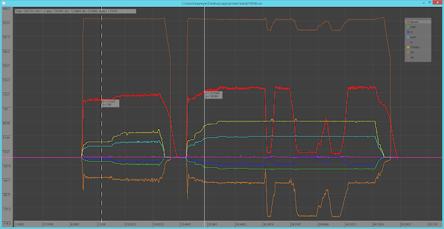
'plotter' and 'logger': Cycle by Cycle Data Logging for Motor Controllers

Ever since I started writing motor control firmware I've been pursuing higher and higher data logging rates. Back in the days of printing floats over 115200 baud serial on an ATMega328 performance was pretty poor, but now that high-performance ARM devices are available with much better SPI and serial speeds and an order of magnitude more RAM, we can do some pretty cool things. The holy grail is to log relevant data at the switching frequency to some sort of large persistent storage; this gives us the maximum amount of information the controller can see for future analysis.

'logger'

logger is less of a program and more of a set of tricks to maximize transfer and write performance. These tricks include:
  • Packed byte representation: this one should be pretty obvious; rather than sending floats we can send approximate values with 8 bits of resolution. While we no longer need commas or spaces between data points, it is important to send some sort of unique header byte at the start of each packet; without it, a dropped byte will shift the reading frame during unpacking and cause all subsequent data to become unusable. I use 0xFF (and clip all data values to 0xFE); if more metadata is required, setting the MSB's of the data values to zero gives us 127 different possible header packets at the expense of 1 bit of resolution. The latter method also gives us easy checksumming (the lower 7 bits of the header byte can be the packet bytes XOR'ed together); however, in practice single flipped bits are rare and not that significant during analysis; as it is usually obvious when a bit has been flipped - conversely, if your data is so noisy that you don't notice an MSB being flipped, you probably have other problems on your hands...
  • Writing entire flash pages at once: this is incredibly important. SD cards (and more fundamentally, all NAND flash) can only be written to in pages, even if there is no filesystem. Writing a byte and writing a page take the same amount of time; on typical SD card, a page is 512 bytes, so buffering incoming data until a full page is received results in a 1-2 order of magnitude improvement in performance.
  • Dealing with power losses: the above point about how important writing full pages is is actually somewhat facetious. Normally, filesystem drivers and drive controllers will intelligently buffer data to maximize performance, but this is contingent on calling fclose() before the program exits - not calling fclose() or fflush() will possibly result in no data being written to the disk. Having some kind of "logging finished, call fclose() and exit" button is not ideal; if an 'interesting' event happens we usually want to capture it, but in the event of a fault the the user is probably being distracted by other things (battery fire, rampaging robot, imminent risk of death) and is probably not thinking too hard about loss of data. The compromise is to manually call fflush() once every few pages to write save the log to disk without losing too much performance. Depending on the filesystem implementation you are using, data may be flushed automatically at reasonable intervals.
  • Drive write latency and garbage collection: this is a problem that nearly sunk the SSD industry back in its infancy. Drives which are optimized for sequential transfer (early SSD's and all SD cards) typically have firmware with very poor worst case latencies. Having the card pause for half a second every few tens of megabytes is hardly a problem when the workload is a few 100MB+ sequential writes (photos, videos), but is a huge problem when the workload is many small 4K writes, as some of those writes will take orders of magnitude longer than the others to write. The solution is to keep a long (100 pages) circular buffer with the receiving thread adding to the end and the writing thread clearing page-sized chunks off of the tail. The long buffer amortizes any pauses during writing; as long as the average write speed over the entire buffer is high enough no data will be lost.
  • Delta compression: I have not tried this, but in theory sending or writing (or both) packed differences between consecutive packets should yield a significant boost in performance by reducing the average amount of data sent. This should be true especially if the sample rate is high (so the difference between consecutive data points is small).
Here is a sample sending program which sends data in 9-byte packets (including header) from a 5KHz interrupt over serial, and here is the matching receiver which writes the binary logs to an SD card with some metadata acquired from an external RTC and IMU module.

'plotter'

I wrote plotter after failing to find a data plotting application capable of dealing with very large data sets. Mathematica lacks basic features such as zooming and panning (excuse me? not acceptable in 2018!), Matlab becomes very slow after a few million points, and Plotly and Excel do all sorts of horrible things after a couple hundred thousand points.


plotter uses a screen-space approach to drawing its graphs in order to scale to arbitrarily large data sets. Traces are first re-sampled along an evenly spaced grid (a sort of rudimentary acceleration structure). Then, at each column of the screen, y-coordinates are interpolated from the grid based on the trace-space x-coordinate of the column. Finally, lines (actually, rectangles) are drawn between the appropriate points in adjacent columns.

The screen-space approach allows performance to be independent of the number of data points, instead, it scales as O(w*n), where w is the screen width and n is the number of traces. It also guarantees that any lines drawn are at most two pixels wide, which allows for fast rectangle-based drawing routines instead of costly generalized line drawing routines (on consumer integrated graphics, the rectangles are several times faster than the corresponding lines). As a result, plotter is capable plotting hundreds of millions of data points at 4K resolutions on modest hardware.

For the sake of generality, the current implementation loads CSV files and internally operates on floating-point numbers. There's a ton of performance to be gained by loading binary files and keeping a 32-bit x-coordinate and a 8-bit y coordinate (which would lower memory usage to 5 bytes per point), but that comes at the expense of interoperability with other programs. The basic controls are:
  • Cursors:
    • Clicking places the current active cursor. Clicking on a trace toggles selection on that trace and puts the current active cursor there.
    • [S] switches active cursor (and allows you to place the second cursor on a freshly opened instance of the program). If visible, clicking on a cursor switches to it.
    • [C] clears all cursors.
  • Traces:
    • Clicking a trace toggles selection.
    • Clicking on the trace's name in the legend toggles selection. This is useful and necessary when multiple traces are on top of each other.
    • [H] hides selected traces, [G] hides all but the selected traces, and [F] shows all traces.
  • Navigation:
    • The usual actions: click and drag to zoom in on the selected box, scroll to zoom in centered around the cursor, middle click and drag to pan.
    • Ctrl-scroll and Shift-scroll zoom in on the x and y-axes only, centered around the cursor.
    • Placing the mouse over the x or y-axis labels and scrolling will zoom in on that axis only, centered around the center of the screen.
  • File loading:
    • plotter loads CSV's with floating point entries.
    • The number of entries in the first row of the input file is used to determine the number of channels. From there on, extra values in rows are ignored, and missing values at the end get copied from the previous row.
    • In Windows, drag a CSV onto the executable to open it. Note that this will cause the program to silently exit with no error information if the file is invalid.
  • Configuration:
    • plotter.txt contains the sample spacing (used to calculate derivatives and generate x-labels), the channel colors, and the channel names. If the config file is missing, all the traces will be black and the channel names will all be 'Test Trace'.
    • The program will crash if arial.ttf is not in the program directory.
You can get a Windows binary here; source code will be uploaded once it is tweaked to work on Linux.

Sunday, January 14, 2018

Fun (?) with an AJA Cion

Long camera is long
It was Black Friday 2017 and I hadn't bought anything. Thankfully, the fine folks at LensAuthority were running a special on the AJA Cion, an oft-maligned CMV12000-based camera  It was real cheap, cheaper than a CMV12000 machine vision camera, and probably more ergonomic as it had the capability to record ProRes internally to proprietary or Cfast 2.0 media at 60p.

General Impressions

You probably don't want this camera for general cinematography; the sensor is noisy enough that you will be spending a ton of time fighting the camera. For example, a simple interior shot of MITERS proved to be too much for the sensor, and MITERS is not exactly a high dynamic range scene. This is further compounded by the fact that the noise is heavily patterned; some rows are noisier than the others (not to be confused with FPN!), which is a lot more distracting that having white noise distributed over the image. And forget about available light shooting, the only ISO you get is 320 (500 and 800 are a joke, the sensor has little enough DR even with no gain applied). Folks can go on about 'great color science' and 'ready to edit codec' all they want, but it is hard to justify a $5K camera with barely 10 stops of dynamic range when the Ursa Mini 4.6K falls in the same price class and is so much better at everything.

The handling...is adequate. The fact that the menus don't show up on the monitoring outputs really puts a damper on operation, as the operator cannot see the settings while the camera is rigged up and shoulder mounted. Even on a tripod, using the click wheel to scroll through 30 menu entries is unpleasant, especially when you can only see one row of the menu at a time (come on AJA, give us a firmware update that fixes this!). Thankfully, operation is very slick when the camera is tethered through an Ethernet cable and operated through the browser interface - the embedded website is intuitive and, more importantly, doesn't seem to exhibit the inconsistent hangups and crashes that plague a ton of my other Ethernet controlled gadgets.

The real strength of this camera, in my opinion, is as a specialized, tethered camera. 4K120 raw is rather state of the art; no other "consumer" camera on the market can do this (RED and Kinefinity can do high framerate wavelet-compressed recording though). As for capturing the HFR output...

Raw Recording

...I'm not sure how I feel about quadruple SDI based output. On the one hand, SDI capture cards are readily available and well-standardized, and I would certainly take four BNC's over one CameraLink cable any day. On the other hand, multi-tap SDI capture is a mess right now (not all cards support combining their inputs out of the box), and RAW transport over SDI is basically a scam, with recorder vendors charging hundreds of dollars for the software licenses to enable RAW recording for each supported camera model.

Image from AJA's site
The only officially supported ways to record the 120p output are via a device called a 'Corvid Ultra' (some sort of $20K box that plugs in via Tesla-style PCIe HIC's), or using an AJA Kona4, a $1995 quad 3G-SDI capture card. The Kona software (AJA Capture Room) has a preset for CION RAW (confusingly enough, the button in the software is not where the manual says it would be). This seems to set each tap as 2K60p, so presumably each frame from each tap encapsulates two consecutive quarter-frames of the full image. It should be possible to record the output as four uncompressed 2K60p Quicktime files on several third-party capture devices, then merge the frames in post; unfortunately, as of this writing there are no small 60p-capable SDI capture devices - all models available have an integrated monitor.

The officially recommended hardware to capture 120 FPS raw is absurd: start with an HP Z820 and a pair of LSI 9721, each equipped with four Intel S3700 or six (!) Intel S3500 drives in RAID 0, then stripe the two RAID 0 volumes together (!!) in Windows to create one large virtual drive. Come on guys, even when the release notes were last updated (2015), NVMe drives and 3D NAND were a thing. I also don't understand the suggestion to use enterprise drives; clearly, if you are running octuple RAID 0 across two RAID cards, you've given up any hope for reliability. A single OCZ RD400 or 960 Pro (512GB or higher) can handle the throughput (even when the drive is nearly full), and a pair in RAID 0 should more than do it. Or, if you feel bleeding edge, a single Optane drive should be able to do it with unbelievable consistency.

For the sake of size, my recording box uses a i3-7100 and a single 512GB RD400 drive; the rather low-performance CPU seems to be OK for Capture Room (which uses a whole core to debayer the preview but otherwise doesn't consume much CPU power). 512GB was chosen as the minimum size needed to achieve the requisite worst-case write speeds, but offers an incredibly mediocre six minutes of recording at 120 FPS. It is important to note that Skylake/Z170 is the oldest "small" platform where the chipset PCIe ports are PCIe 3.0 - anything older and you risk degrading the recording drive's performance.

Capture Room

AJA Capture Room is...very good. This was unexpected, as I am used to very expensive scientific hardware shipping with LabView or Java based garbage that makes your computer feel like its from 1999. At least on Windows, the UI doesn't feel as native as I'd like it to be, and sorting out the dozens of configuration options for the Kona4 requires reading a PDF manual, but I haven't had a crash, and more importantly, it can extract the full performance of the SSD. A lesser program would require 2x overhead to be able to run properly, but clearly someone at AJA actually cared about performance.

Image Quality

(or lack thereof)

Cinema DNG processed to taste in Capture One
The above test scene was shot on a 24mm Art at f/1.4 and processed as a still in Capture One. Exposure was 360 degrees (1/120) and 120 FPS. The primary defect that stands out is the noise in the background; the scene was processed with a 'flat' tone curve that boosted the shadows a substantial amount. The banding (which is caused by the read noise being spatially correlated, not "fixed pattern noise") is incredibly distracting; it is visible in the resulting video as a bright lines scrolling vertically in the shadows. That being said, the colors look beautiful, and you could easily shoot this scene with some fill light and avoid the noise problem altogether.

The other problem is Resolve doesn't process the RAW's nearly as well as C1 does, as it uses fast GPU implementations of pretty basic algorithms. For example, the only sharpening available is a simple unsharp mask; there is no attempt to intelligently detect structure in the image, resulting in sharpening being unusable in the presence of noise. Is the solution to output JPG's from Capture One into Premiere Pro? Probably not; having a program which natively handles raw video is amazing, and so much less clunky than a cobbled together stack of software.

Addendum: a bug appears!

Upon further inspection of the footage, it appears that 120p footage is only recorded as 60p by capture room. AJA insists it is because the computer isn't fast enough, but I think it is due to a bug in Capture Room - among other things, setting the buffer to 4K60p in AJA Control Panel instead of 2K60p results in the correct data rate, but Capture Room segfaults at exit and the resulting files are not usable.